
Do, or do not. There is no try. –Yoda
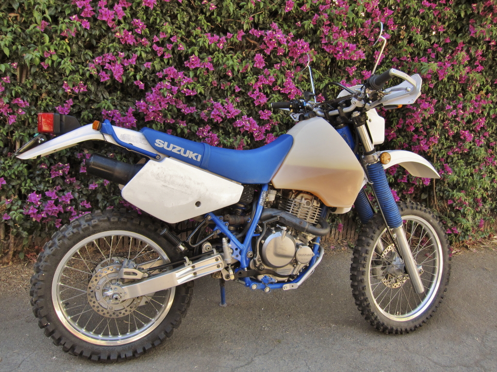
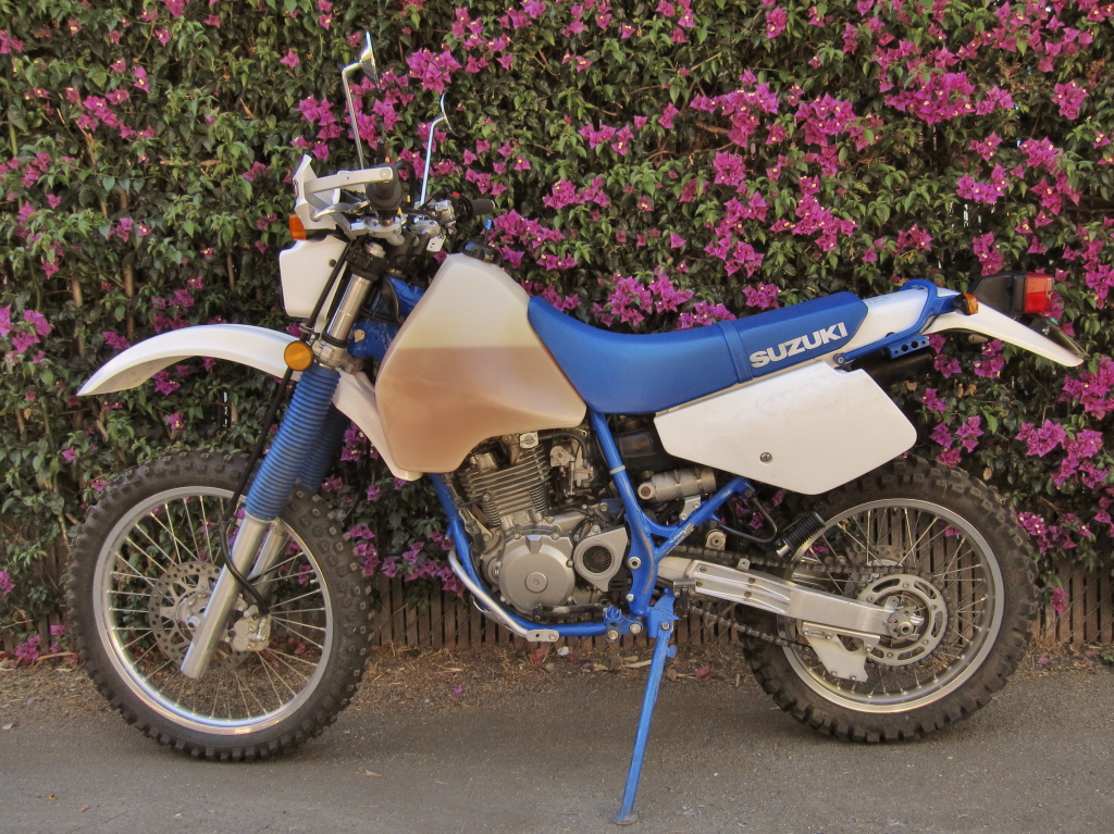
Suzuki DR350, ready for its valve check
Going In: Checking and Adjusting Valves on a DR350
The latest challenge in the maintenance series is an old-school enduro/dual sport bike: a 1992 Suzuki DR350. These bikes have single-cylinder, overhead cam engines with screw-and-locknut valve adjusters (as well as a dry sump engine, which we’ll get to when I change the oil). They’re relatively simple, and a good place to start if you’ve never gone deep and adjusted valves previously.
Suck, Squeeze, Bang, Blow
What do valves do? Without going into a full exposition of four-stroke engine theory, the valves serve as spring-loaded doorways into the combustion chamber or cylinder. The DR350 has only one cylinder (making it a “thumper”), and four valves: two intake, and two exhaust. As the engine’s camshaft rotates, it presses the intake valves open, first allowing the fuel/air mix to fill the cylinder (the intake stroke), then closing as the piston moves up to the top of the cylinder, AKA Top Dead Center (the compression stroke, and the point you want to adjust from). At that point the spark plug ignites the fuel-air mix (the power stroke), pushing the piston back down to the bottom of the cylinder; finally, on the exhaust stroke, the piston swings back up to Top Dead Center and the exhaust valves open, allowing the exhaust gases to escape, and the cycle begins again.
To help you understand What’s Going On In There, here’s an animation of a 4-stroke, single-cylinder engine at work. The only differences are that what is labeled the “inlet” valve is what riders usually call the “intake” valve, and on the DR350, a cam chain instead of a timing belt connects the camshaft and the crankshaft.
When the valves are closed, they need to seal tightly against the valve face and the valve seat (in the cylinder head) to prevent the escape of exhaust gases. To make sure that the valve seats securely, there needs to be a bit of lash or freeplay between the narrow stem of the valve and the rocker arm. In screw-and-locknut designs like the DR350, this can be adjusted via, well, a screw and locknut on the top of each rocker arm!
Valves live hard, hot lives. When the freeplay/lash on any valve tightens up below spec, it spends more time open, rather than in its valve seat. Timing is affected and exhaust gases can leak, which will lower performance or even prevent starting–but more urgently, the valve can’t transfer as much of its heat to the surrounding aluminum of the seat. This can lead to engine overheating or a bent or burned valve. Loose valves make more noise, but are less serious; the valve stem may be damaged by the hammering of the adjuster. And while loose valves may clatter loudly, too-tight valves are deadly silent, though they can cause hard (or no) starting and uneven idling. So, time for a check!
Tools, Concentration, Readiness
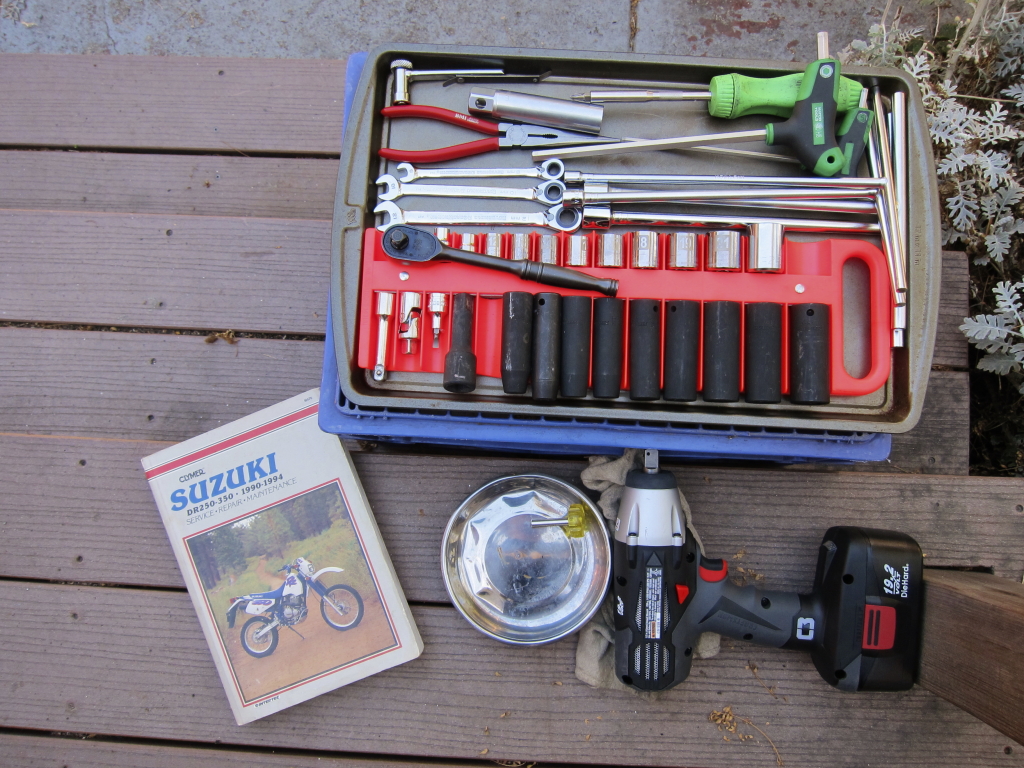
Block out plenty of time to do the job undisturbed; leaving the bike unbuttoned and returning later might allow parts to get scattered, and make you forget where everything went, what the clearances were supposed to be, and that you forgot a set of pliers somewhere they shouldn’t have been. Organize your tools and your workspace so that everything is easily at hand, and arrange to get help if you need it. A stand for the bike and a couple of tables and/or trays to organize tools can be helpful to set up, if you aren’t working in a garage with toolboxes at hand.
The manual (a key component of your tool collection) suggests checking the valves on a DR350 every 600 miles or so; fortunately, it’s relatively easy on this bike.
A rule for all valve checks is that the bike must be absolutely cold: heat expands metal, in the valve train as everywhere else in the engine, and will throw off your clearance readings. Wait til the bike is good and cold, preferably overnight. The DR hadn’t been ridden since the day before.
I had my head, my schedule, and my tools together, so it was time to go in.
Do or Do Not, There is No Try
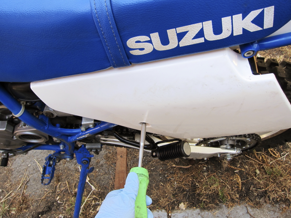
The bike needed to be stripped of its side panels, seat, and gas tank to make the valves accessible. Fortunately they’re all simple, quick to remove and easy to reach on the little Suzuki.
I removed the side panels,
then the seat (2 12mm bolts),
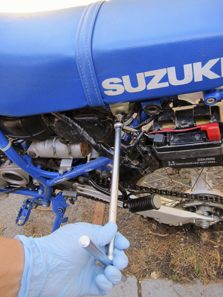
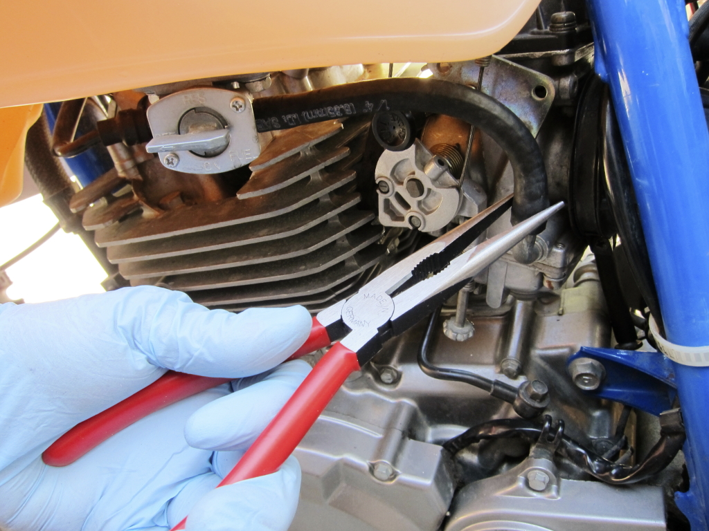
and then the fuel tank, which involved turning off the petcock to stop the flow of gas, pulling off the gas line with pliers, and removing the 12 mm bolts from the tank, then lifting it away. I set the panels, seat and tank in a safe spot so I wouldn’t trip over ’em.
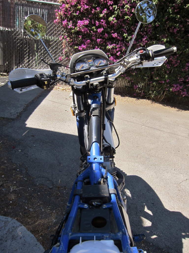
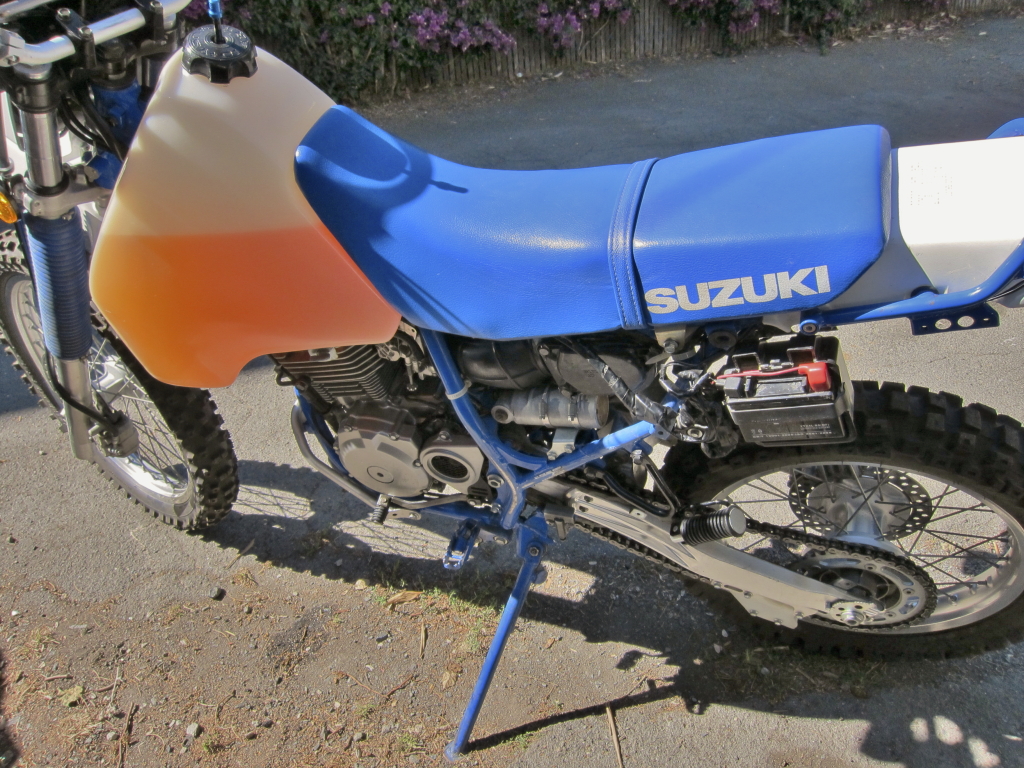
The bike is now stripped down, and the caps covering the crankshaft nut and valves are accessible, as is the spark plug.
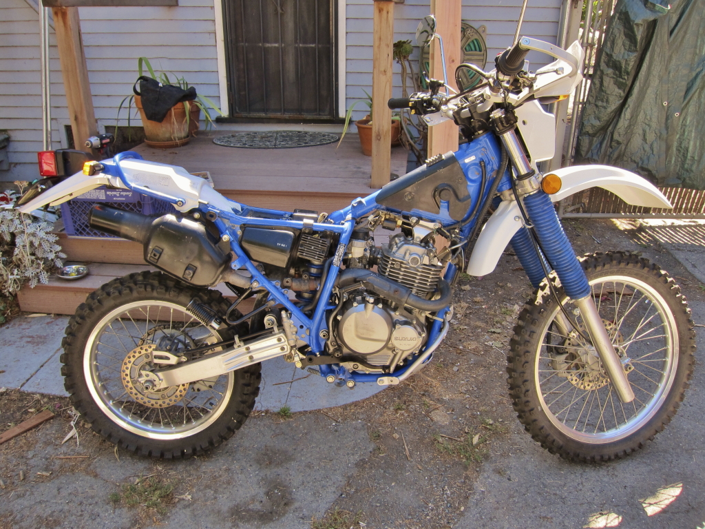
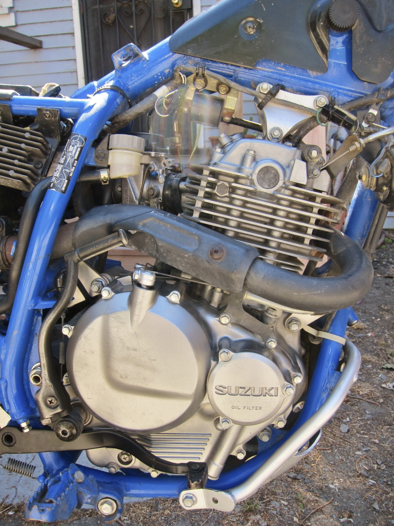
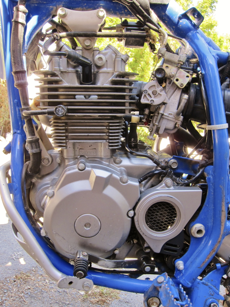
Here are right and left side views of the engine I was working with.
I flipped my manual to the valve check/adjust procedure, read through all the steps, and noted the specs for the valve clearances.
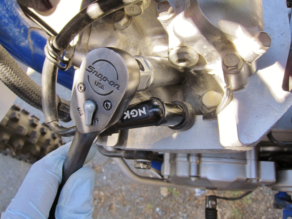
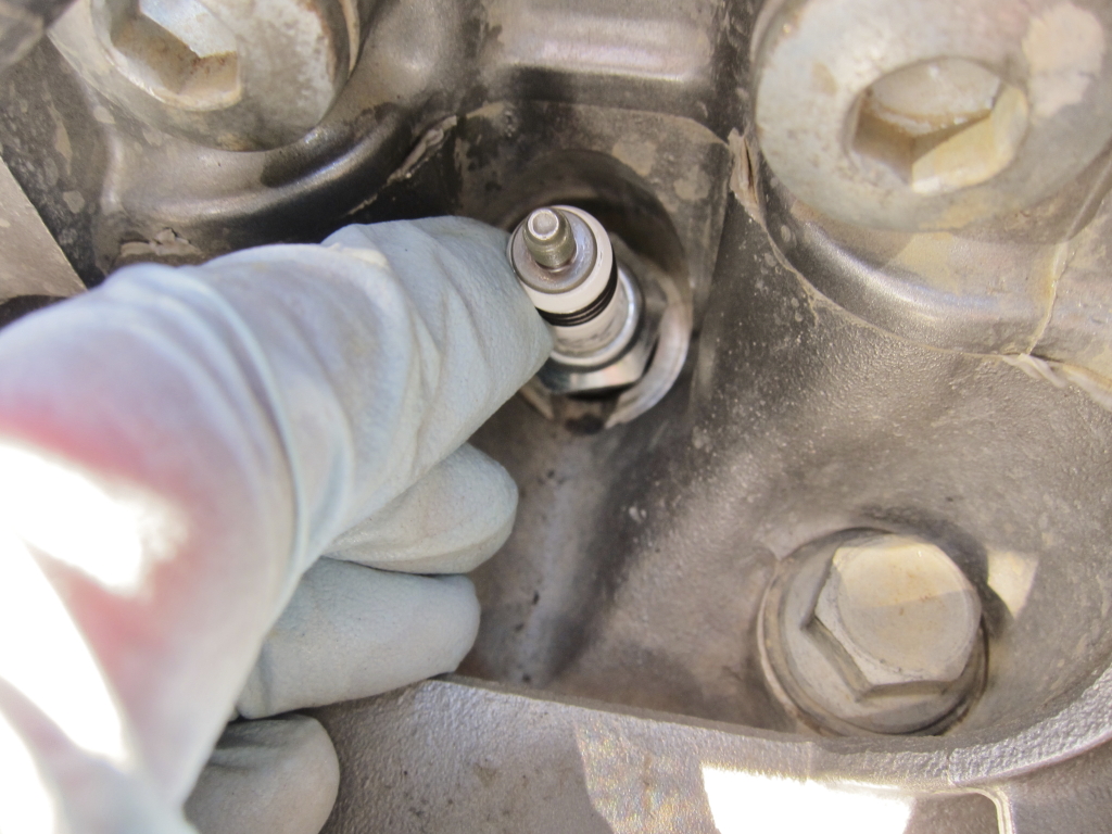
With the manual out, tools ready and the bike stripped down, it was time to pull the spark plug wire from the spark plug, then use my thin walled Motion Pro brand 18mm spark plug socket and remove the plug. Before pulling it, I made sure there was no dust, dirt or debris in the area to fall into the spark plug hole and wreak havoc on the engine.
With the spark plug out, I moved to the valve cover caps, removing first the exhaust valve cap,
Exhaust Valve Cap removal
and then the intake valve cap, and setting them carefully aside.
Intake valve cap comes off
I checked the valve cover o-ring for flat spots and cracks.
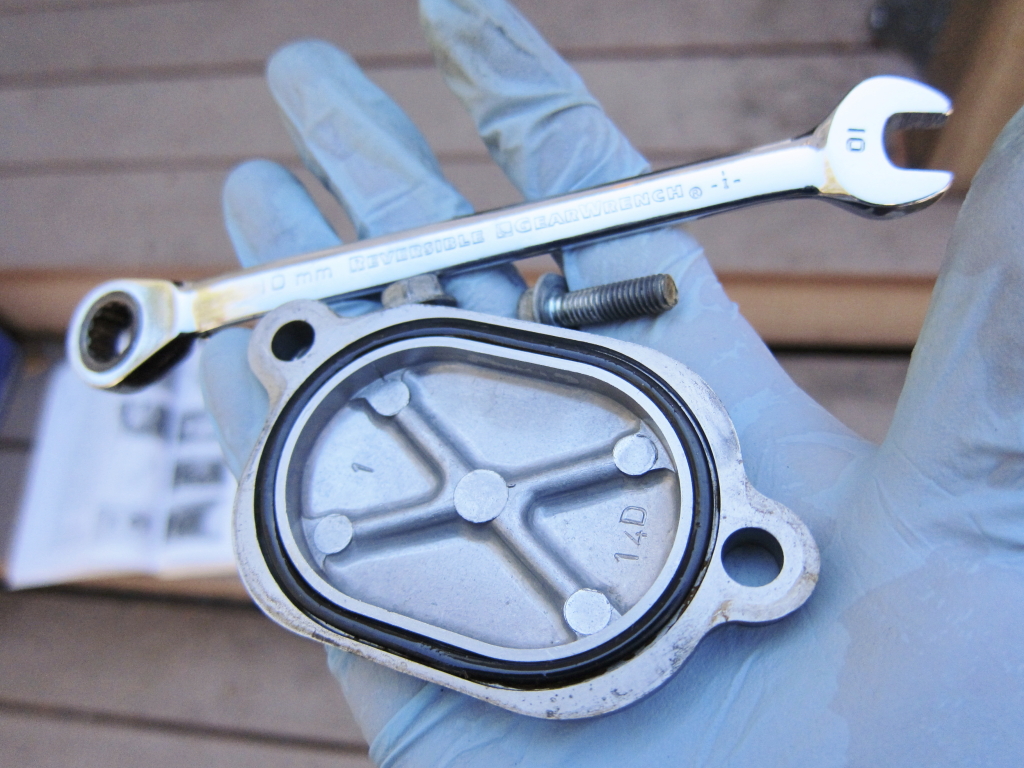
Valve cap and 10mm wrench, o-ring is in good shape
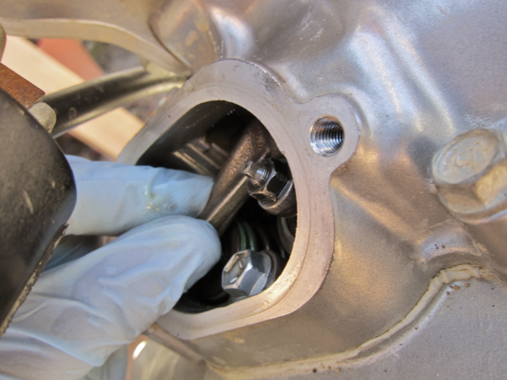
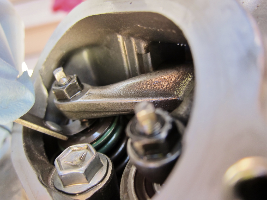
Under the cover, the valve springs, the screw adjusters, and the rocker arms were visible.
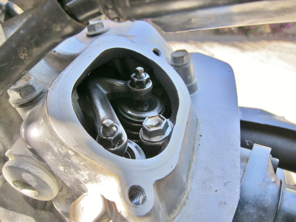
Beneath the cover, the rocker arms
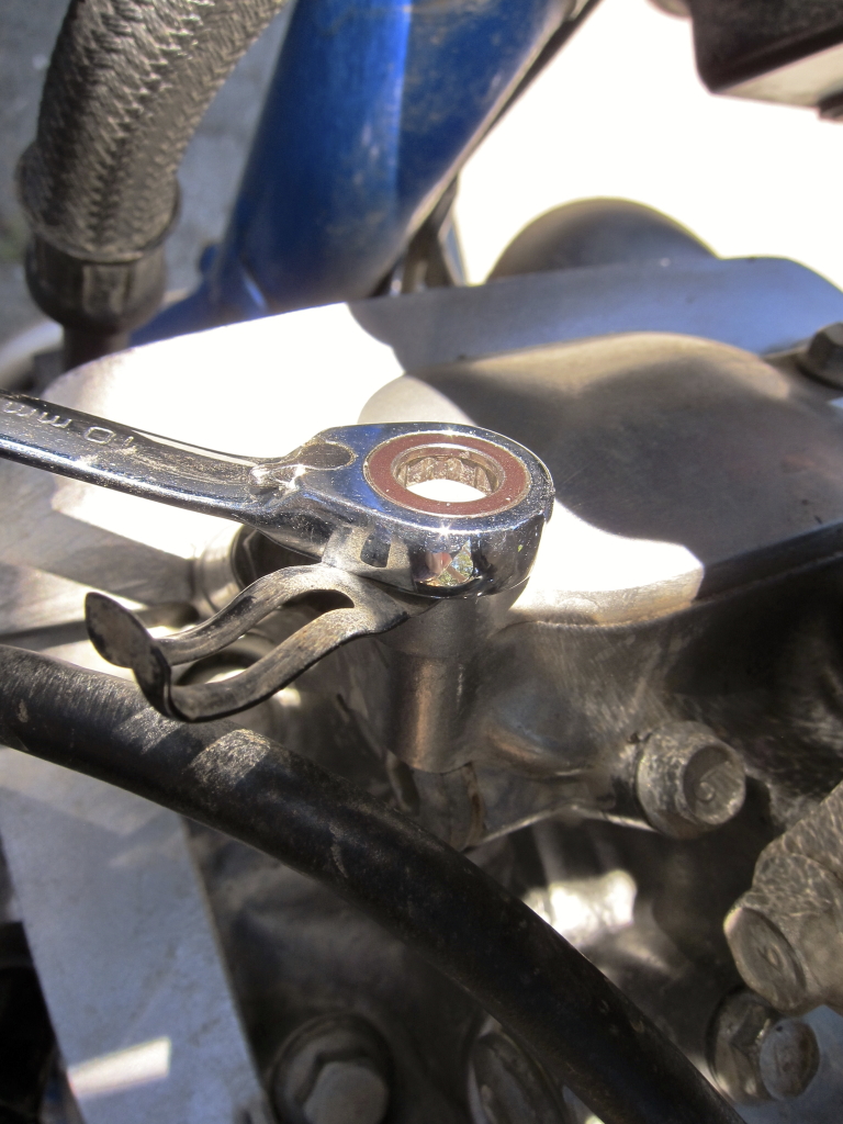
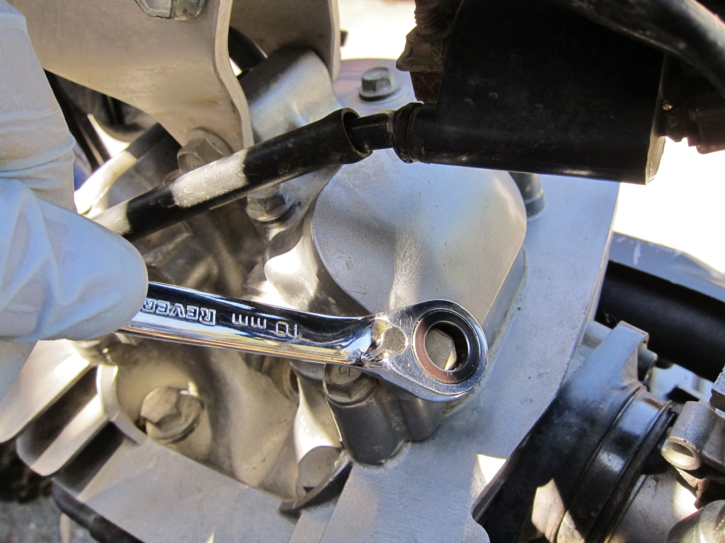
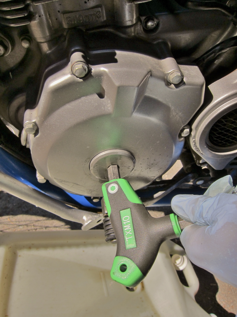
I used a 10mm allen wrench to undo the magneto/stator cover cap to expose the rotor bolt, being careful not to strip the soft aluminum in the process.
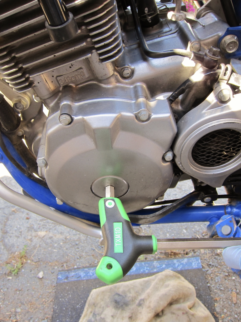
Undoing the magneto cover
When the cap came off, some of the oil drained out (the bike was sitting on its sidestand, after all), and I slid my oil pan under the bike to catch the drips. The next step was changing the oil, anyhow.
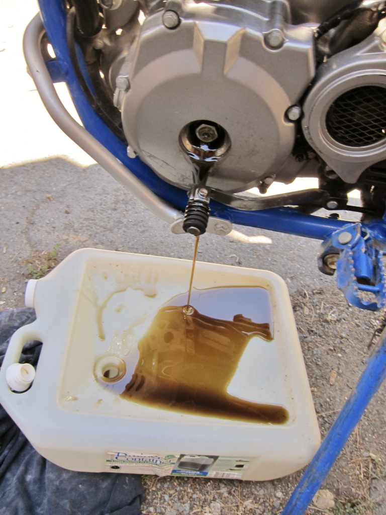
Be ready to catch the oil when the cover is removed
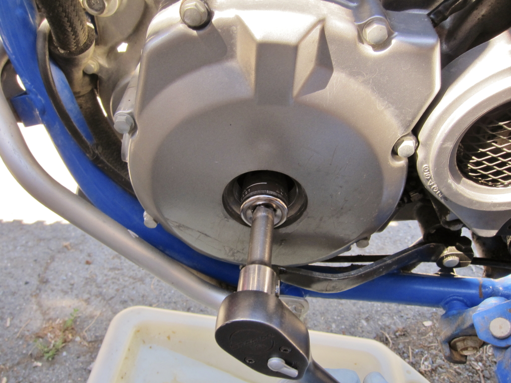
I used an 8mm allen wrench to remove the cap that covers the timing mark. When I rotated the rotor to find Top Dead Center (TDC), the mark on the flywheel indicated when I was in the right spot.
Removing the timing mark cap
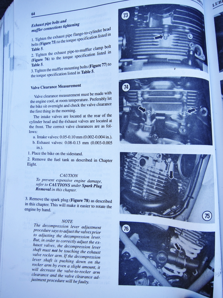
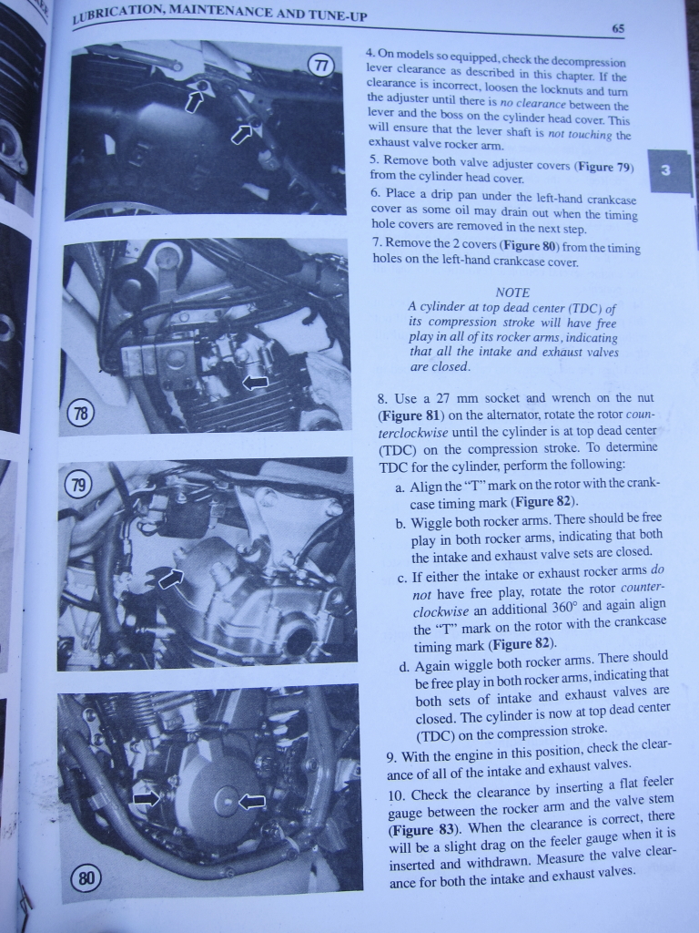
Before checking the valves themselves, the engine needs to be in the correct position. For each revolution of the crankshaft, there are two positions at which the piston moves up and reaches TDC: once on the exhaust stroke, and once on the compression stroke (remember the video of the 4 strokes in the engine cycle?). Only one is the correct position to accurately check the valve lash–TDC on the compression stroke, when the valves are closed. If you check the valve lash while the engine is on the exhaust stroke, the valves will be open and you’ll get an inaccurate reading. Fortunately determining which of the two revolutions the bike is on is pretty easy, since there’s only one piston in a single-cylinder bike!
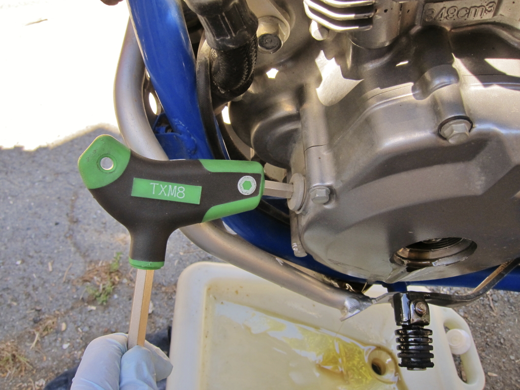
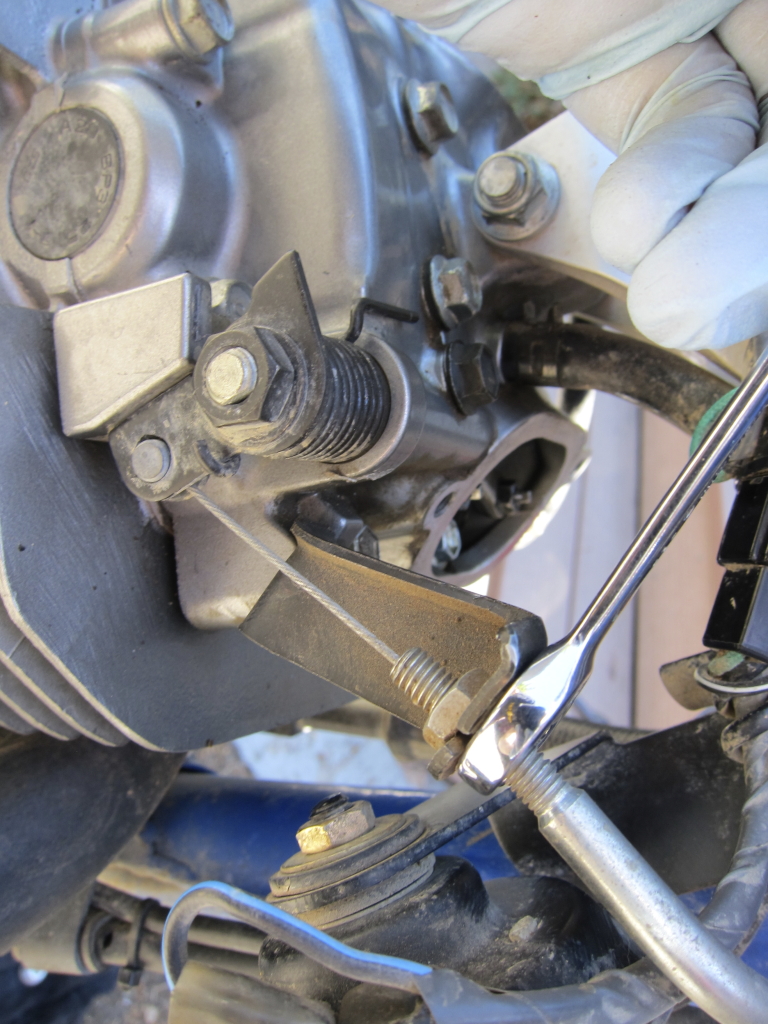
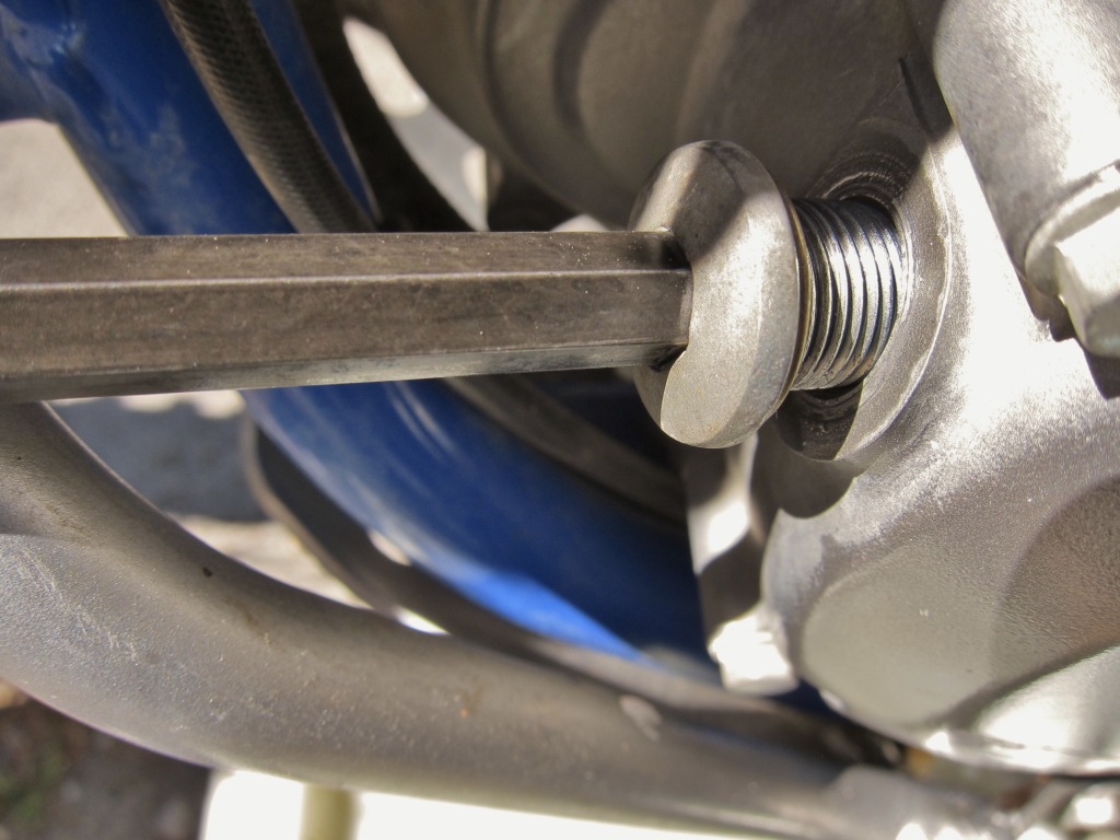
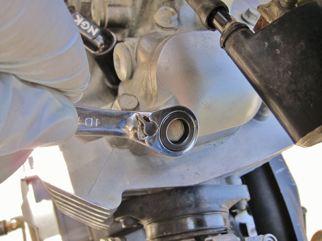
This meant that I needed to turn the crankshaft counterclockwise using a 17mm socket and a short extension (the 27mm in the manual is a typo) placed on the rotor or crankshaft bolt, while looking for the “T” mark to come around and become visible in the small sight window. When you do, stop turning and check to ensure that the engine is positioned correctly. It’s entirely possible to see the TDC mark through the sight window, but have the engine at TDC on the exhaust stroke by mistake–you’ve got a 50% chance, in fact (remember, the engine hits TDC again, one full turn of the crankshaft apart, on the exhaust stroke and the compression stroke). To make sure you are on the compression stroke, one method is to reach up and grab a rocker arm and wiggle it up and down. If there is a small but discernible rattle, you’ve hit the right spot. If not, turn the rotor bolt 360 degrees, look for the TDC mark in the sight window again, and try once more to rattle the rocker arms.
If you’re unsure, there’s another method, too–grab a narrow cylindrical object like a chopstick or a long screwdriver (nothing that can easily break off), and slide it down into the spark plug hole. If the engine is at TDC of the compression stroke, your probe will hit the face of the piston quickly. If it extends all the way down into the cylinder, you’re on the exhaust stroke; pull out your probe, turn the crank a full revolution and try again.
17 mm socket on the rotor bolt, turning counter-clockwise
In my case, I peered through the timing mark hole, saw the T mark indicating TDC, and then tried to wiggle the rocker arms–no luck. I was one turn off, on TDC on the exhaust stroke. I cranked the rotor around counterclockwise again, and stopped when I saw the T mark once more.
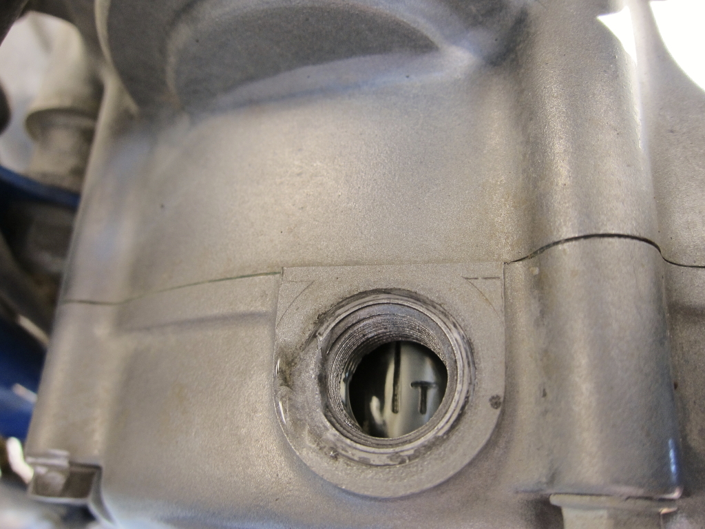
TDC mark seen through sight window
Now I felt some free play in those rocker arms–I was in the right spot to begin the valve clearance check.
Wiggling rocker arms to verify TDC
One more thing to do before going in–make sure the decompression cable stop is not interfering with the rocker arm on the exhaust valve (which would throw off the exhaust valve clearance reading). I loosened the cable slightly, so the stop on the cable wasn’t touching the rocker arm, reminding myself to adjust it back when I was done.
Loosening the cable for the decompression lever
Learning to Feel Clearance
Minor moment of truth: it was time to check and, if necessary, adjust the valve lash.
The clearances for the DR350’s valves are:
Intake valves: between 0.05–0.10 mm (0.002–0.004 in.)
Exhaust valve: between 0.08–0.13 mm (0.003–0.008 in.)
I have a couple of convenient Motion Pro feeler gauges that have angled blades, and are the proper thickness for checking the DR350’s valves. A regular old set of graduated feeler gauges would work just fine, as well.
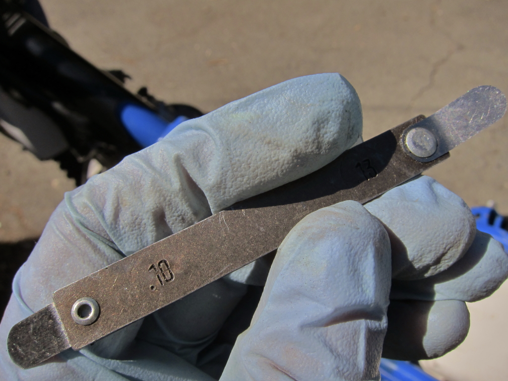
Feeler Gauge for checking clearance
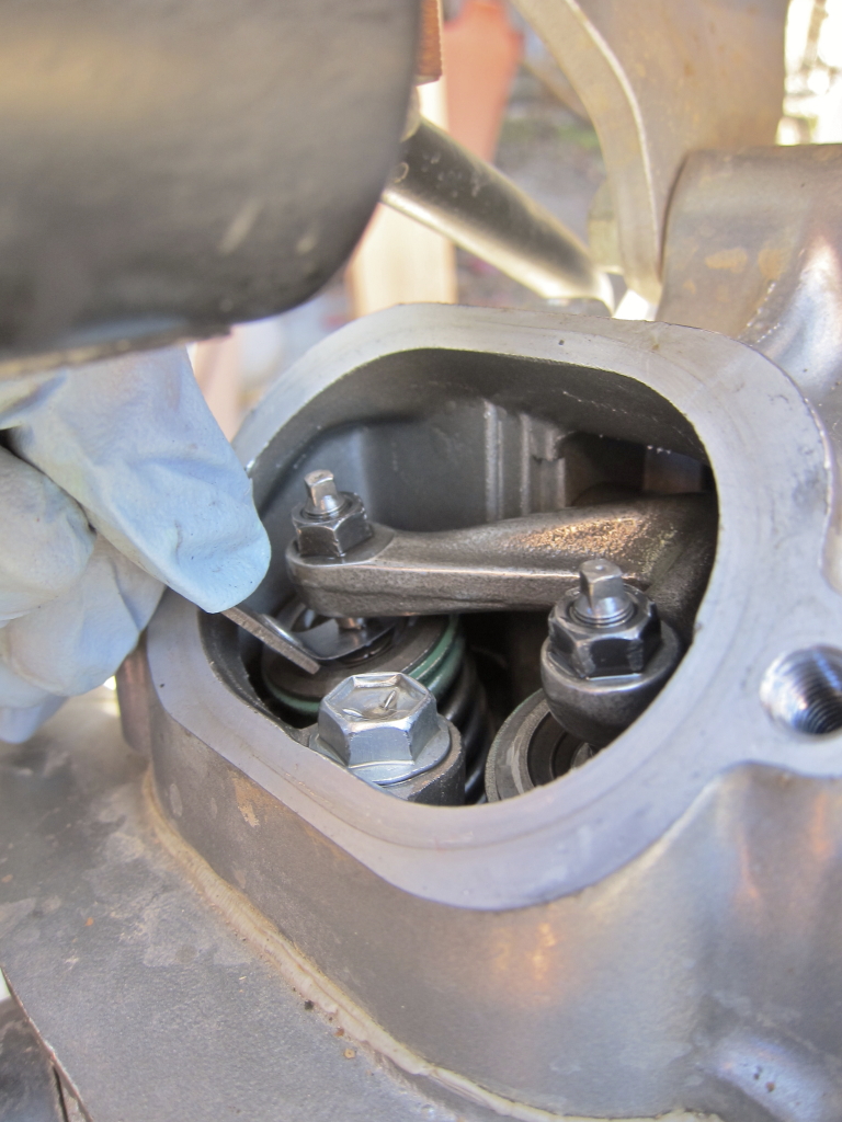
I then slid the feeler gauge between the valve stem and rocker arm on each intake valve. I started with the 0.05 mm blade of my feeler gauge, finding it very loose–it swished right through the space between with no resistance. I then moved up to the 0.10 blade of the gauge, and found it to be just a bit too tight–I had to force the blade between the stem and rocker. This meant that the actual valve clearance was somewhere in between 0.05 and 0.10–precisely in spec. The other intake valve was the same. I was lucky–the intake valves needed no adjustment.
Sliding the feeler gauge between the valve stem and rocker arm
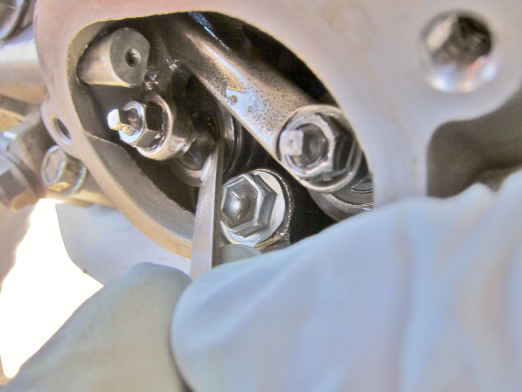
Next I moved forward to the exhaust valves. Somewhat paradoxically, the exhaust valve side faces the front of the bike–near the spot where the exhaust headers are attached to the engine (the intake valves are near the air intake).
Slipping the feeler gauge between the valve stem and rocker arm, I checked the clearance, looking for a range between 0.08mm and 0.13mm. Developing a feel for the resistance on the feeler gauge when checking valves is important: ideally, the gauge should pass between the parts with a slight resistance that feels, to me, like scotch tape peeling off wood, metal or plastic. Too loose and the gauge just whisks right through; too tight and you have to force the gauge in a little. In this case, I was able to fit the 0.15mm feeler gauge through the gap in one of the exhaust valves, which meant that it was too loose.
Checking exhaust valves
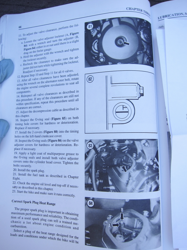
This meant that it was time to grab my Motion Pro valve adjustment tool (a small wrench-within-a-wrench tool that fits over and turns the small square adjuster, inside the tube of a larger holder, which holds the locknut). I placed it over the locknut of the too-loose valve, turned the long handle counterclockwise to loosen the nut, then used the knurled handle of the smaller adjuster wrench to tighten the adjuster slightly. I re-tightened the larger locknut with the larger wrench, and tested the clearance with the feeler gauge again. This time it was within the 0.08-0.13 spec.
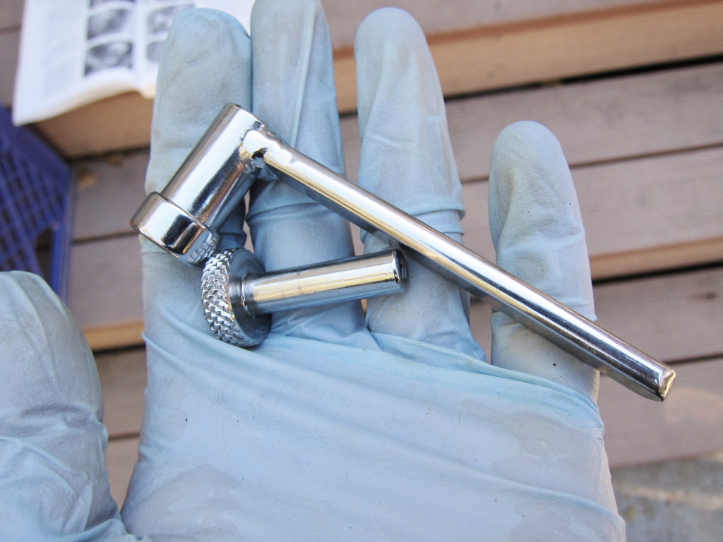
Motion Pro valve adjustment wrench–the small knurled section fits over the adjuster, and slips into the outer wrench, which loosens the locknut
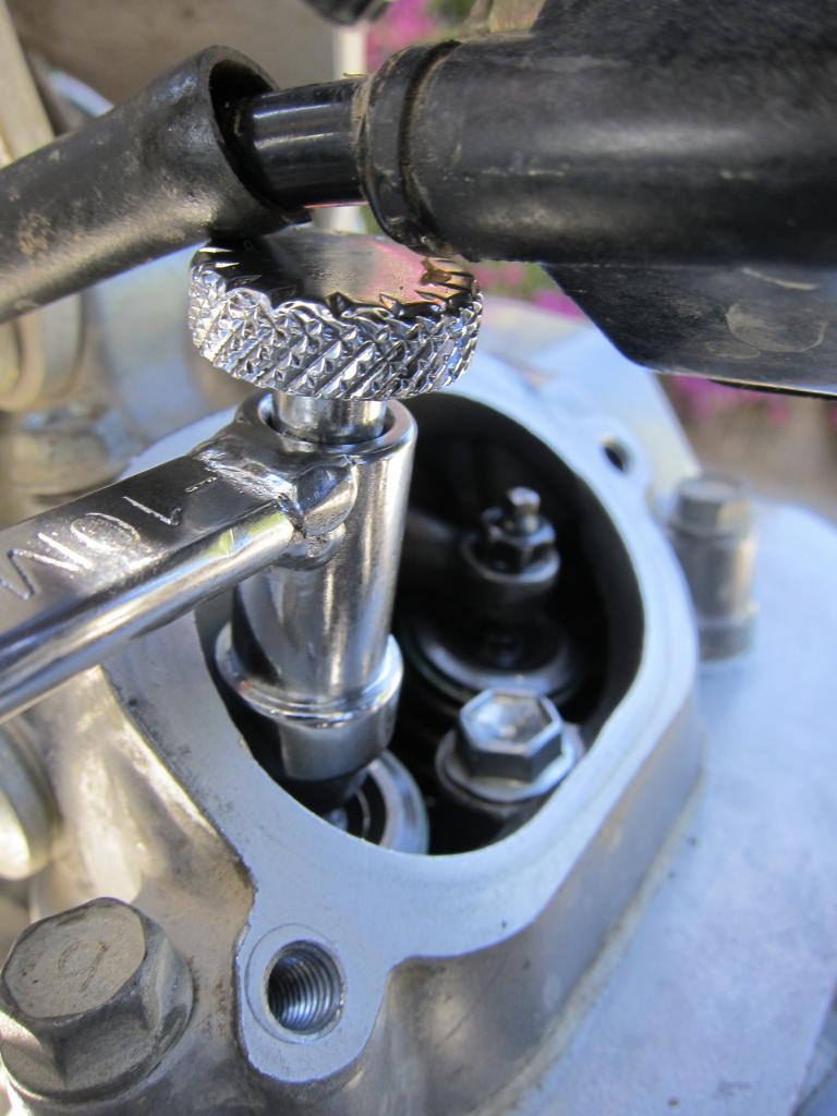
Using the Motion Pro adjuster to tighten up exhaust valves
Sometimes you have to “chase” the right valve lash: you adjust the screw and locknut, test with the feeler gauge again, and it is either too loose or too tight. Just keep adjusting and testing, loosening the locknut and turning the adjuster, then testing with the feeler gauge, until it’s within spec.
Verifying my adjustment–spot on!
I was done with the adjustment, so it was time to toss in a new spark plug (with a touch of anti-seize added to the threads, of course) and button up the bike.
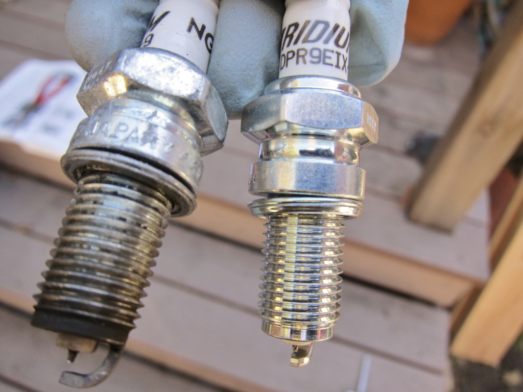
Old vs. new spark plugs
I checked the area of the spark plug hole for debris, and carefully hand-threaded the spark plug in before tightening it with a socket wrench to avoid a cross-threaded spark plug hole.
New spark plug in place
I replaced the timing mark cover,
Replacing the 8mm bolt covering the timing mark
and then the magneto bolt cover,
Replacing the magneto bolt cover
and finally the valve inspection caps (after checking both o-rings for wear, breakage and flat spots, of course).
Replacing the valve inspection caps
I replaced the seat and tank, remembering to hook up the fuel line.
Tank and seat bolted back on, only needs the sidecovers
I added the sidecovers.
Valves checked and adjusted, back together, ready for some exploring!
With that, and a feeling of accomplishment, I was ready for the next step–an oil change!
it’s hard to keep it absolutely while measuring, so there’s a risk of getting too much of a gap.
The straight type of feeler gauges, I mean.
Motion Pro sells three sizes of tappet (valve) adjusting tools. Anyone now the sizes of the two nuts? It’s not in the manual that I can find.
Check that. One of the three is for slot heads, so not the DR.
Say, how does having an automatic compression release change the drill (’99 DR350SE)?
Any idea what to do when we accidentally strip the magneto bolt cover (10mm),, I just tried quick steel with no luck:(
I used a sharp chisel on mine, take the chisel and hit the magneto bolt cover in the CCW direction as far out from the center as you can. Yes it will leave a mark, but at least it gets the job done. I then tightened it with the hex key and haven’t touched it since. Also, warming the bike up a but might help if it’s being stubborn, mine came out first tap with the hammer.
On a thumper TDC will ALWAYS bring the piston to the top of the cylinder regardless of whether or not it’s on the compression or the exhaust stroke. The chopstick method will not work for this. It’s more necessary in multiple cylinder application. You wiggle method is the way to go. Or just simply watching the exhaust values as you turn the crankshaft. Thank you for the write up though very straightforward and well written.
How do I set the timing for(brand)eurojet(model)classique (engine model)1p52qml
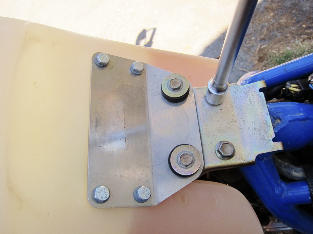
Sweet tank! What’s the make/model/capacity of the tank, and did you have to make any modifications to mount it? Thanks!
You can find on official manual online here:
http://www.thisoldtractor.com/dr350_manuals/workshop_manual_dr350.pdf
Hey paul,
Somehow a roll pin was lodged in the rotor chamber of my DR and it destroyed the stator. I found an excellent aftermarket part. The magneto generates spark but the bike will not fire. It only coughed two times after much kicking.
Is it possible to get the ignition terribly out of timing with the valves? It seems fixed. The stator and the magnet are bolted stationary so if it’s bolted in the way it came out it should be close. Input? TC
nice job, very cool with the pics and all. thanks!
how come you say you used a 21mm socket for the sparkplug, was the old spark plug a dpr9ea9 or cr9ek? what year is the bike?, my plug is 18 mm but still no sockets are thin wall enough its a 1990 dr350 s, also wana know if the cr9ek will work as its listed for the bike on ebay
Bike was a 1992. I don’t own it any longer, so can’t tell you which spark plug–check the Suzuki Owner’s Manual or shop manual for reference. I did use an 18mm thin-walled spark plug socket that is made by Motion Pro to remove the plug, and have corrected the text to reflect that.
use a grinder to grind down a spark plug socket the correct size I have a 1990 pain in the ass but once you have it grinded you can re use it each time
I took a 18 mm and grinded the outside till it fit use it on my klr too.
Did you remember to re-adjust the decompression cable?
Sure did! I should have mentioned that in the blog. If the bike starts poorly after the valve job, it points to the mal-adjusted decomp cable as a likely cause.
Hi thanks for these write ups there very helpful
would u have any on how to fit and set up a decompression lever and cable on a dr350
Sorry, I don’t. When I owned this bike I used the Haynes DR350 repair manual for reference.
thanks i was scare to do it but now i will try
very well done except .013mm is .005 inches not .008.