Engine Autopsy II–What Happened to this V-Strom?

Our deconstruction of an oil-starved Suzuki V-Strom engine continues…
In the last post, I took apart the top end of the engine, finding some cylinder and piston scoring from running the engine dry. Now, to dig down even further into the mystery and find the bike’s exact cause of death.

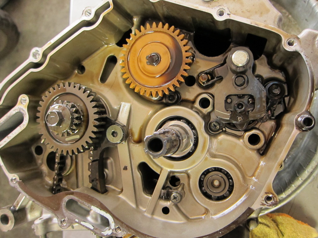
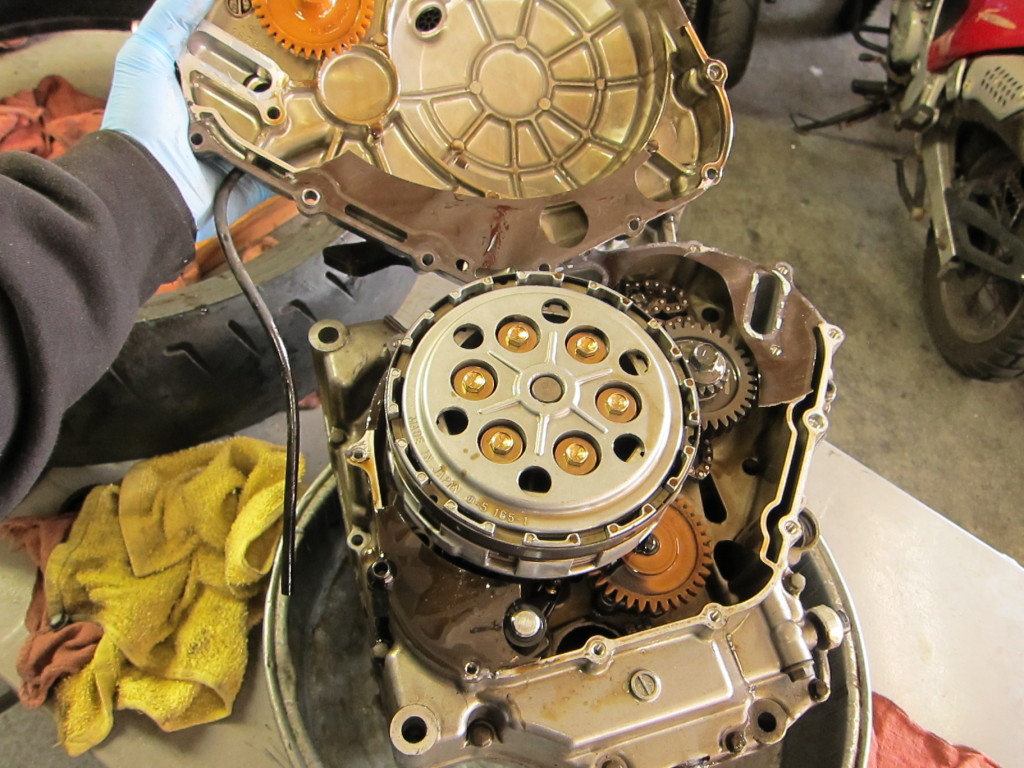
This was our last view last time; the clutch and basket were off, revealing the oil pump gear (orange), the drive shaft (top), and the lower cam chain sprocket (left).

Beneath the clutch

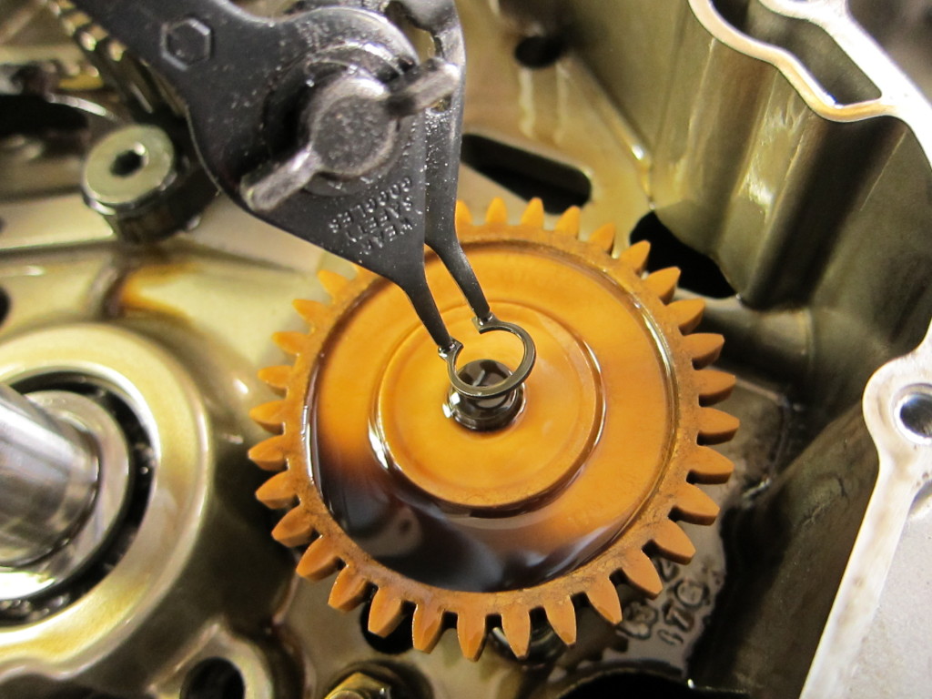
Grabbing the circlip pliers, I lifted off the circlip, then the oil pump gear.

Oil pump gear, held on with circlip

The oil pump had a small transverse pin holding it in place below the oil pump gear. With it out of the way, the oil pump could be lifted out.

Oil pump, freed

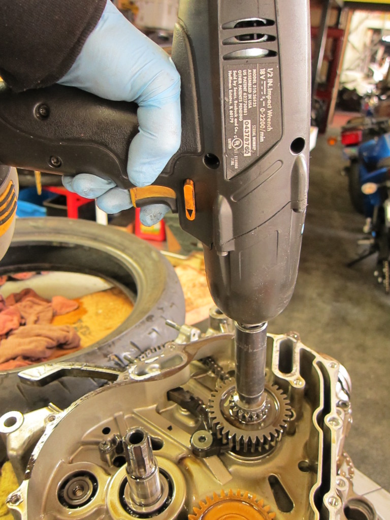
The cam chain sprocket nut was reverse-threaded, and required some bearing down with the rattle gun before budging.

The nut holding on cam chain sprocket comes off with an impact gun

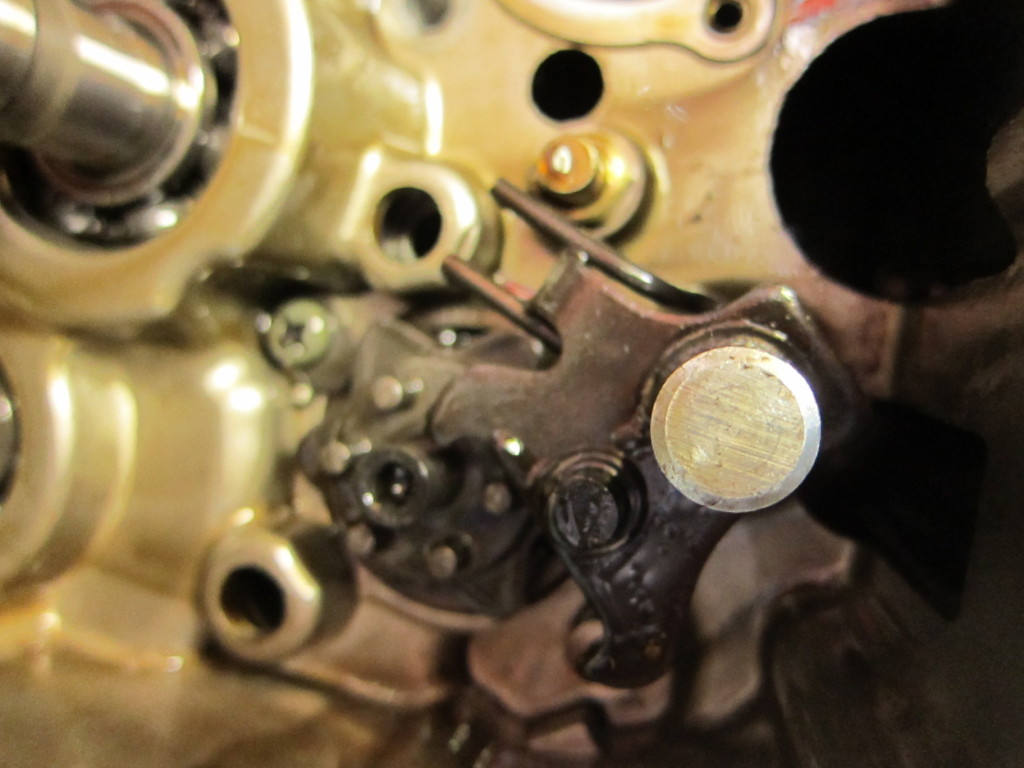
Next it was on to the gear shift plate, with the shift shaft running through the transmission below it.

Gear shift plate--Time to start dismantling the transmission

Beneath the gear shift plate

At that point, I was able to pull the shift shaft from the left side of the engine.

Pulling the shift shaft

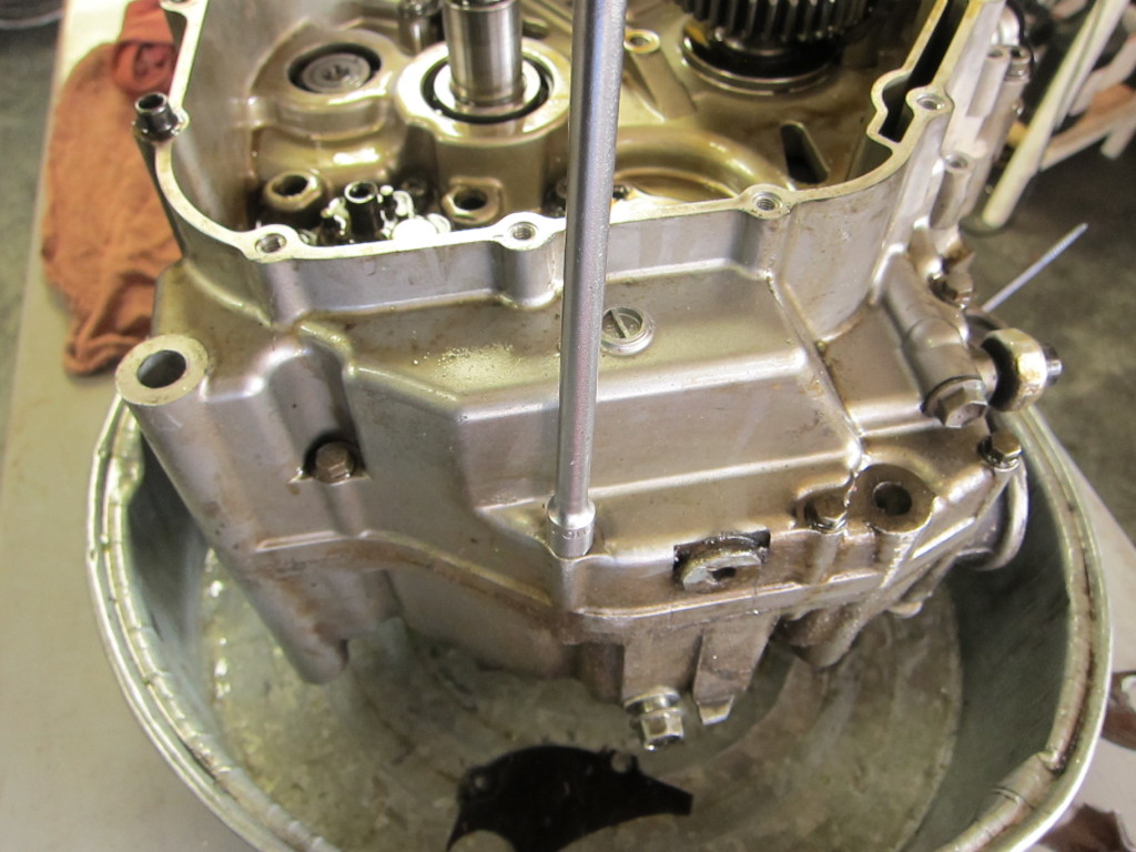
After that was out, I began cracking loose the 8mm case bolts with my trusty T-handle.

Beginning to work on the 8mm case bolts

Closer and closer to splitting the cases...

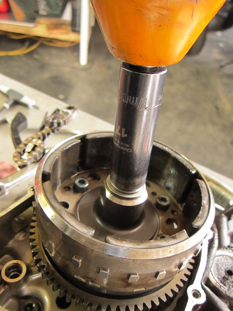
With some of the easily-accessible case bolts out, it was time to turn the motor over and remove the flywheel. The retaining bolt needed an impact gun to get loose.

Flywheel bolt--more work for the trusty impact gun

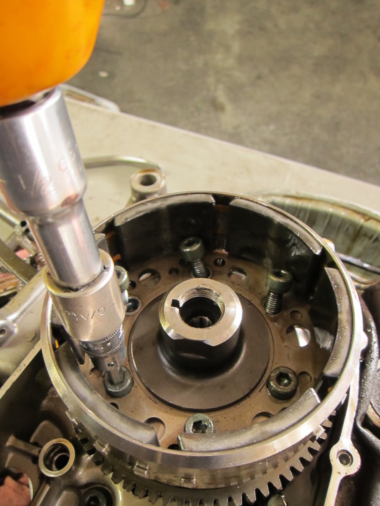
With some effort, it came off. I moved on to the flywheel allen bolts.

Removing the flywheel allen bolts

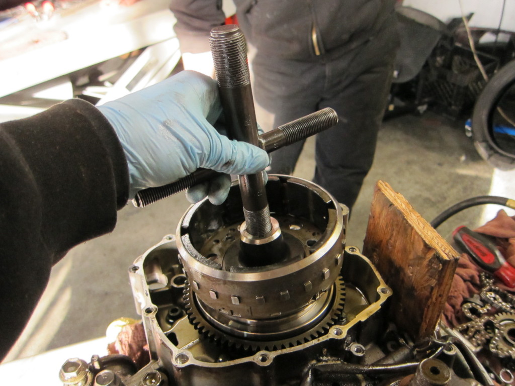
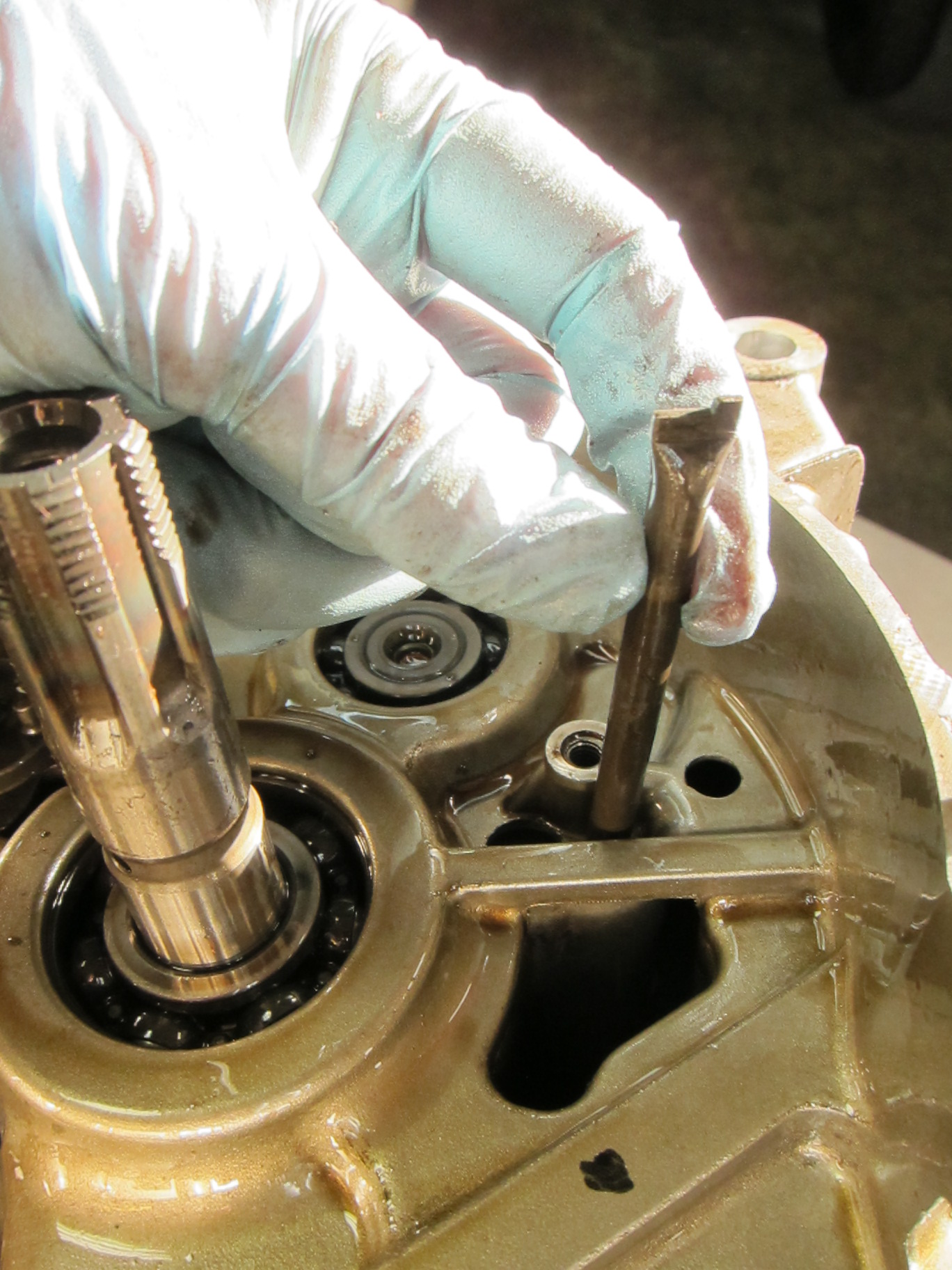
Fortunately the shop has a universal flywheel puller on hand; I threaded in the 22mm size end and prepared to do battle with the flywheel (also known as the rotor). It’s on there very tightly, and has magnets cast into it, so removing it is a memorably sweaty task.

Threading in the flywheel puller

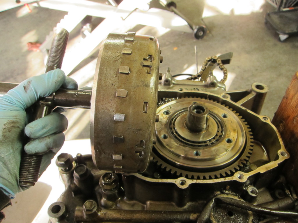
I hammered on that flywheel puller and flywheel with my skinny arms for a while, until the hammer flew out of my sweaty hands and nearly hit my coworker. At last, the flywheel came off with a mighty blow.

Victory! The detached flywheel

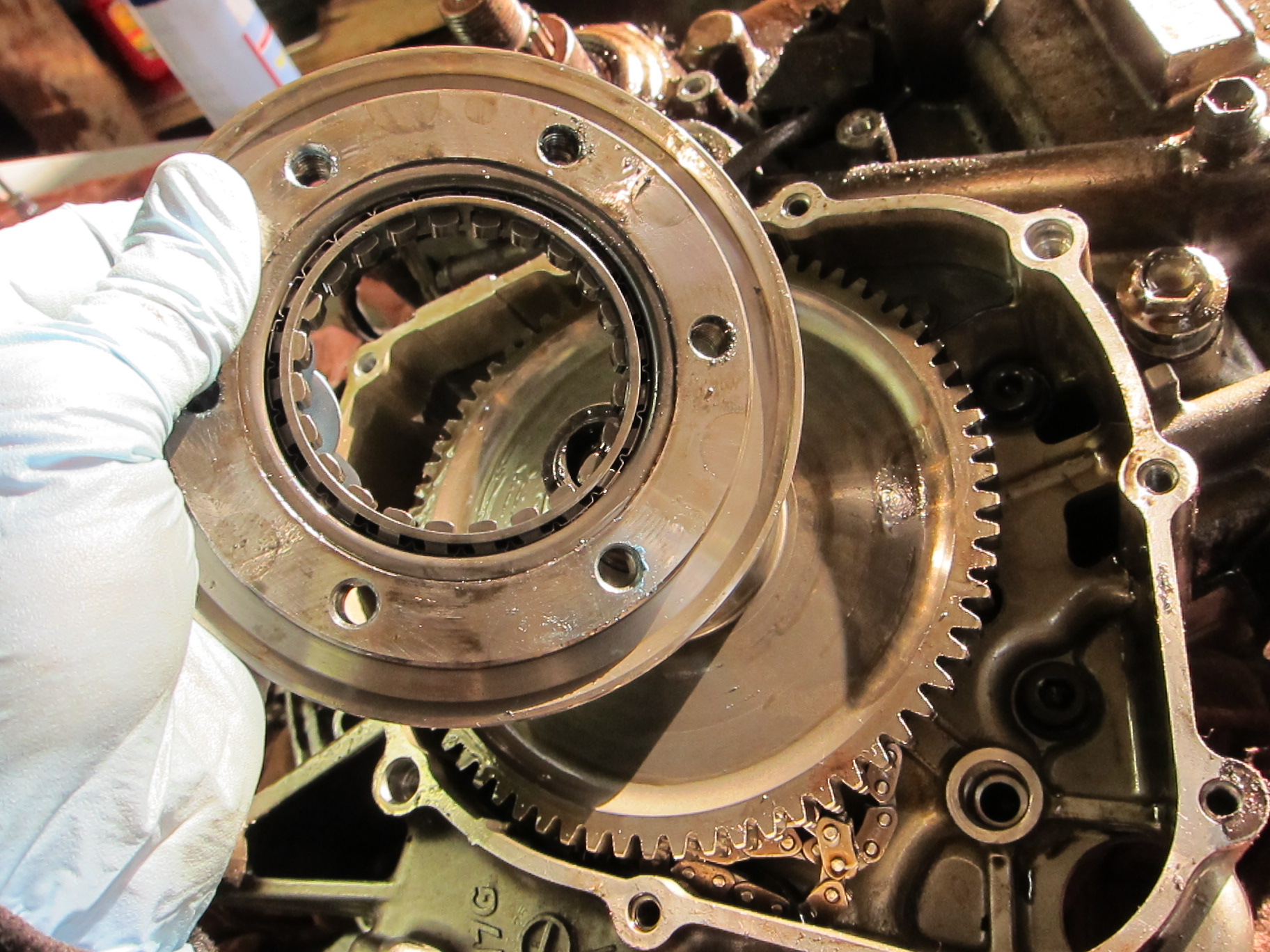
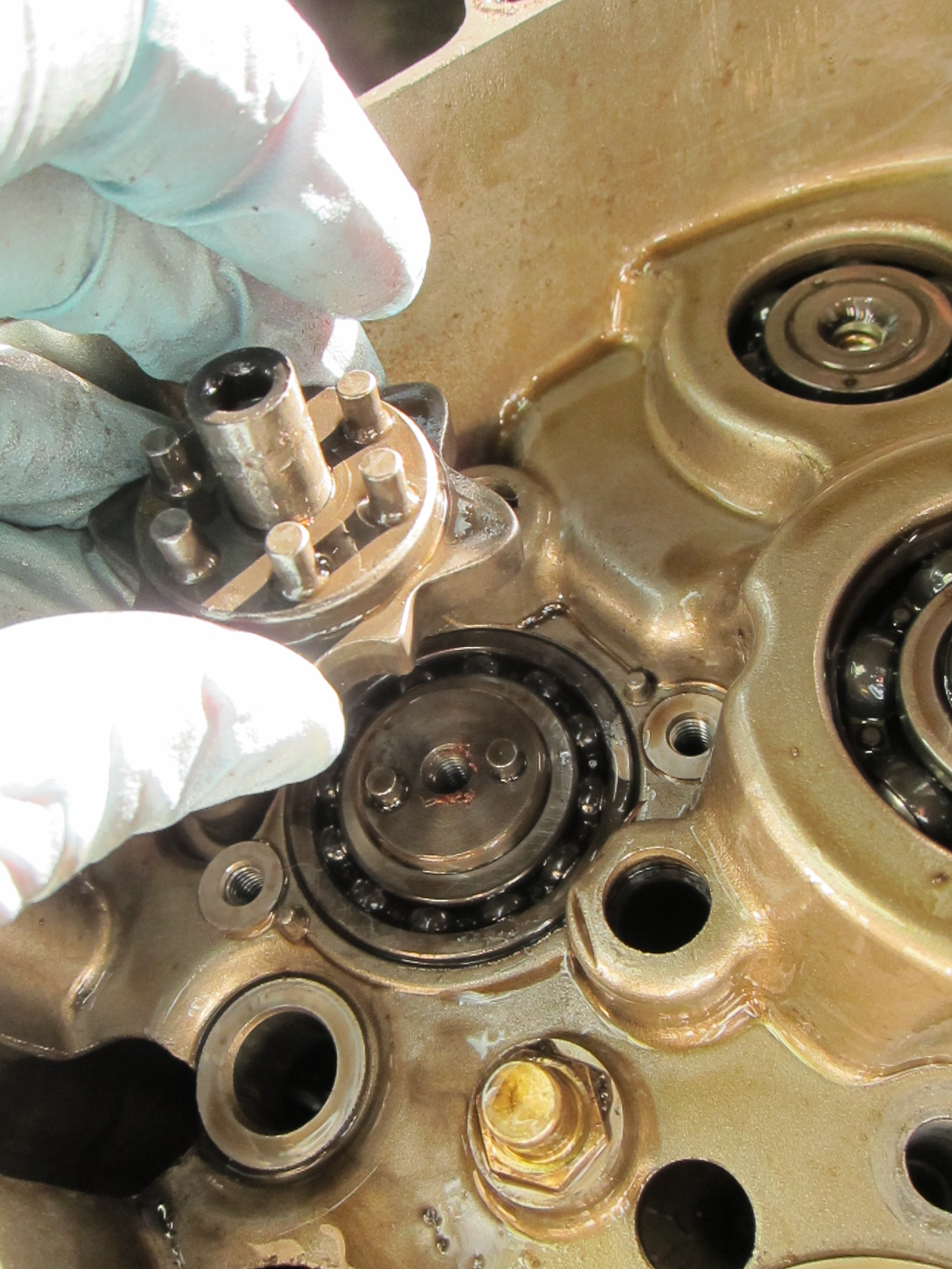
Removing plate and gears below the flywheel/rotor

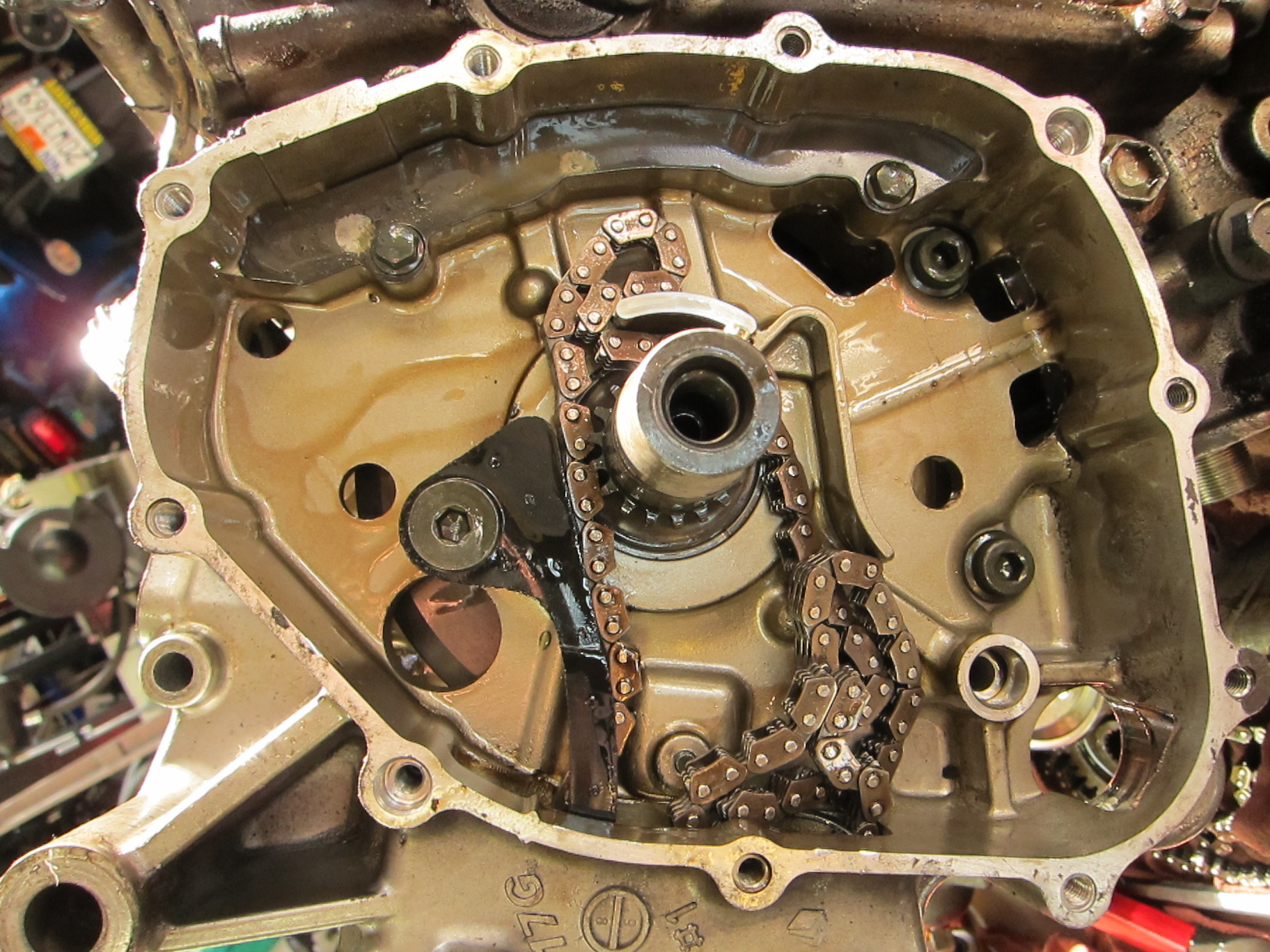
Fascinating slotted insert/worm gear insert beneath the flywheel

With the flywheel and supporting plate and gear gone, the drive shaft was exposed.

Crankshaft exposed--note loose cam chain

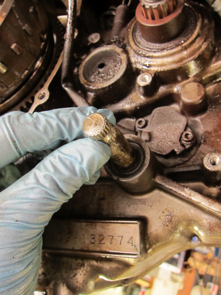
Then there were a few loose ends to clean up before splitting the cases; I pulled the oil pipe and the star gear from the transmission.

Removing an oil line rod to prep for splitting cases

Removing the transmission star gear

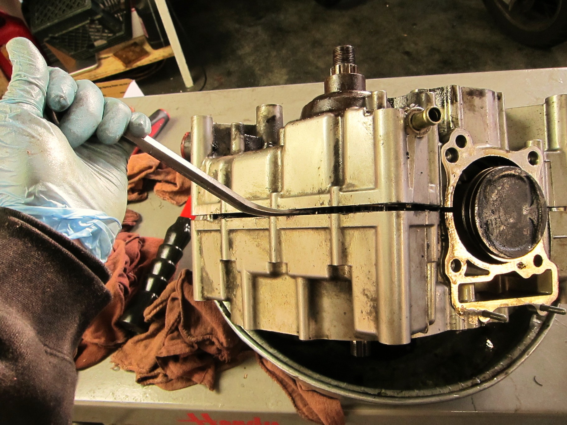
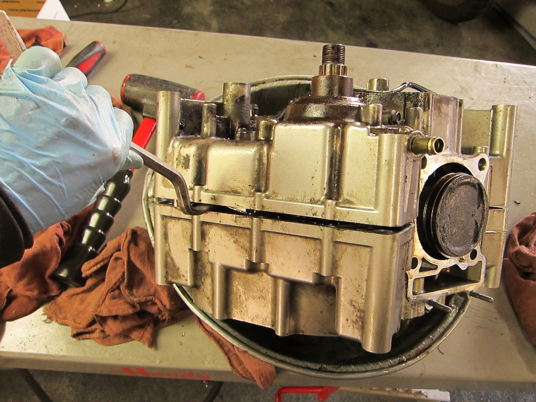
And now, the moment I’d been waiting for–it was time to split the cases. It was my first time, prying apart the halves of the engine to get into the bottom end, to penetrate the secrets of its demise; and it felt like a rite of passage into the realm of internal combustion. I gently worked in my miniature pry bar and began to tap the cases apart with the soft-faced mallet.

The moment of truth--splitting the cases

With a great deal of tapping and gentle prying, the halves began to pull apart.

The case halves, coming apart

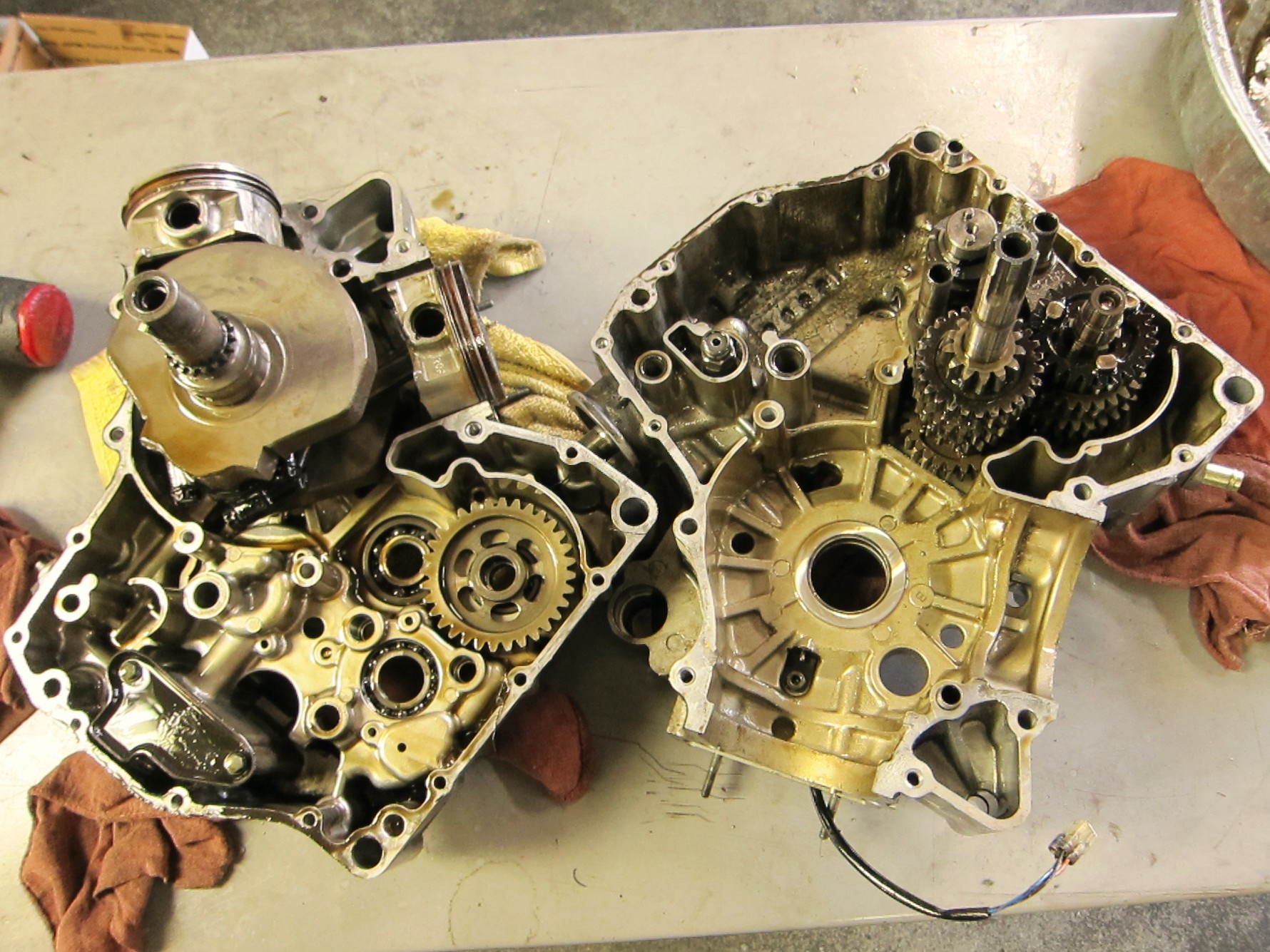
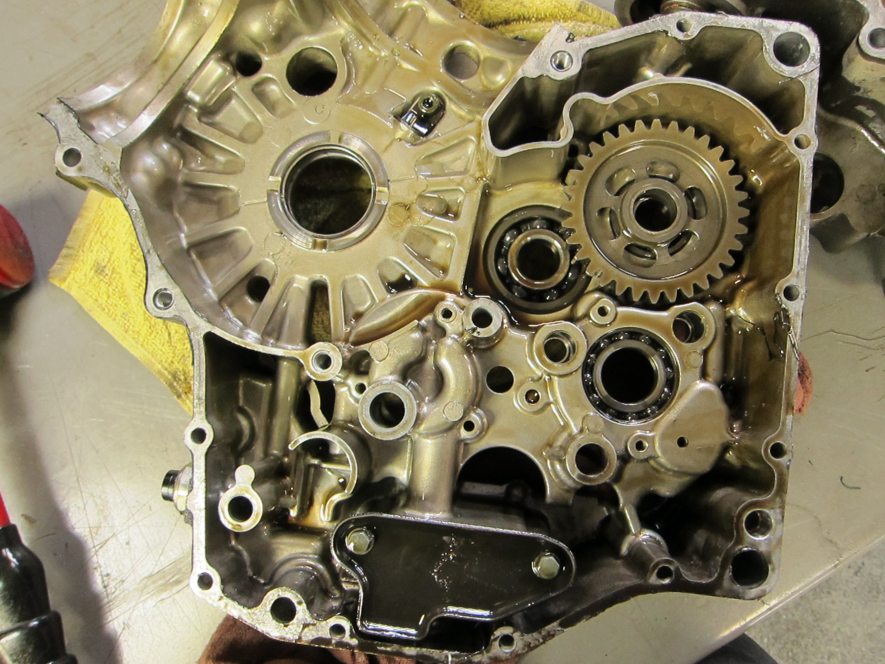
And at last, the halves of the crankcase fell apart, revealing all that lay within.

Halves of the crankcase, apart. Note exposed crankshaft on the left.

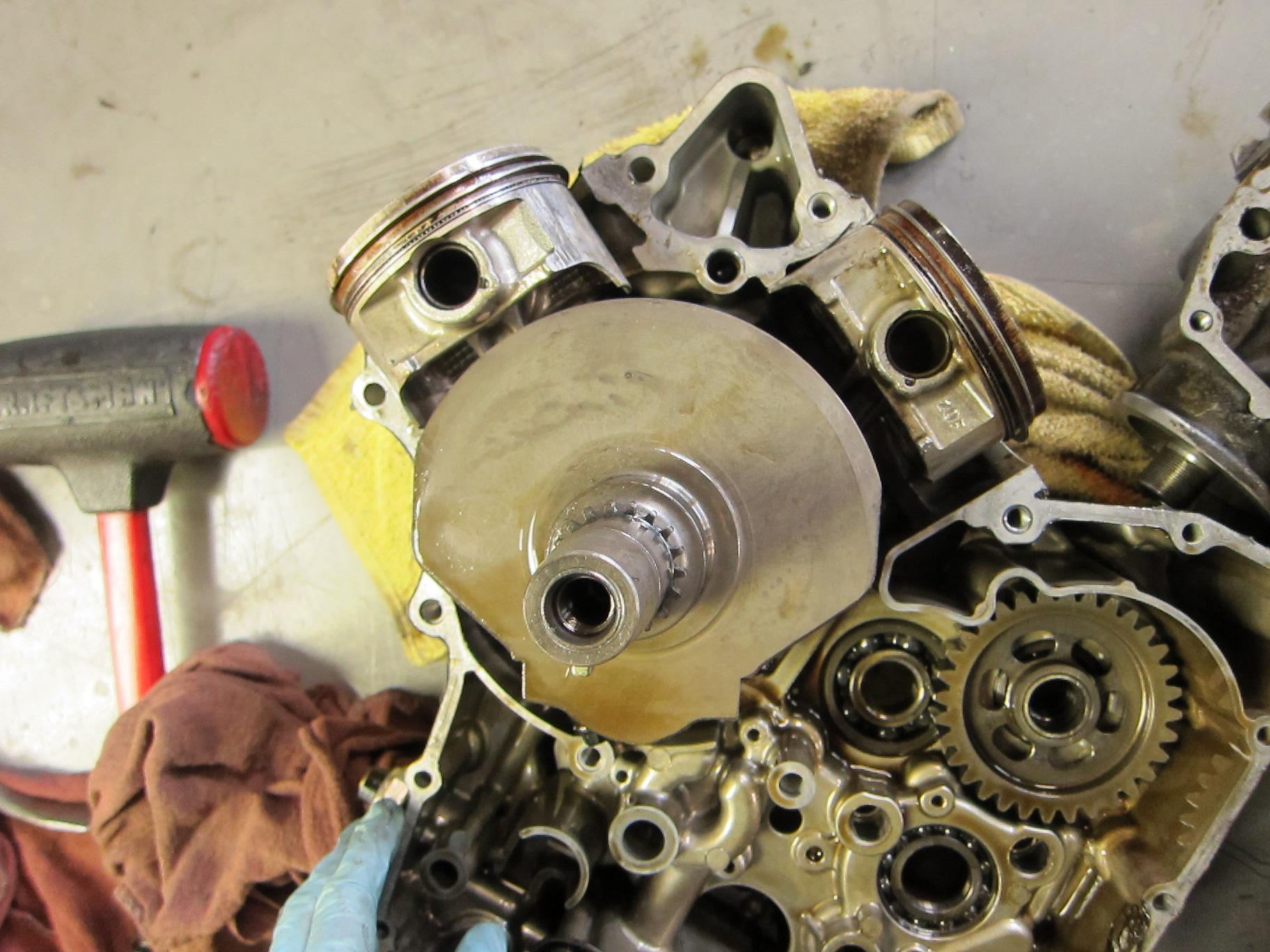
I lifted out the crankshaft and the pistons.

The crankshaft, with pistons attached

In the other half of the crankcase, the transmission gears and dogs were now visible.

Transmission gears

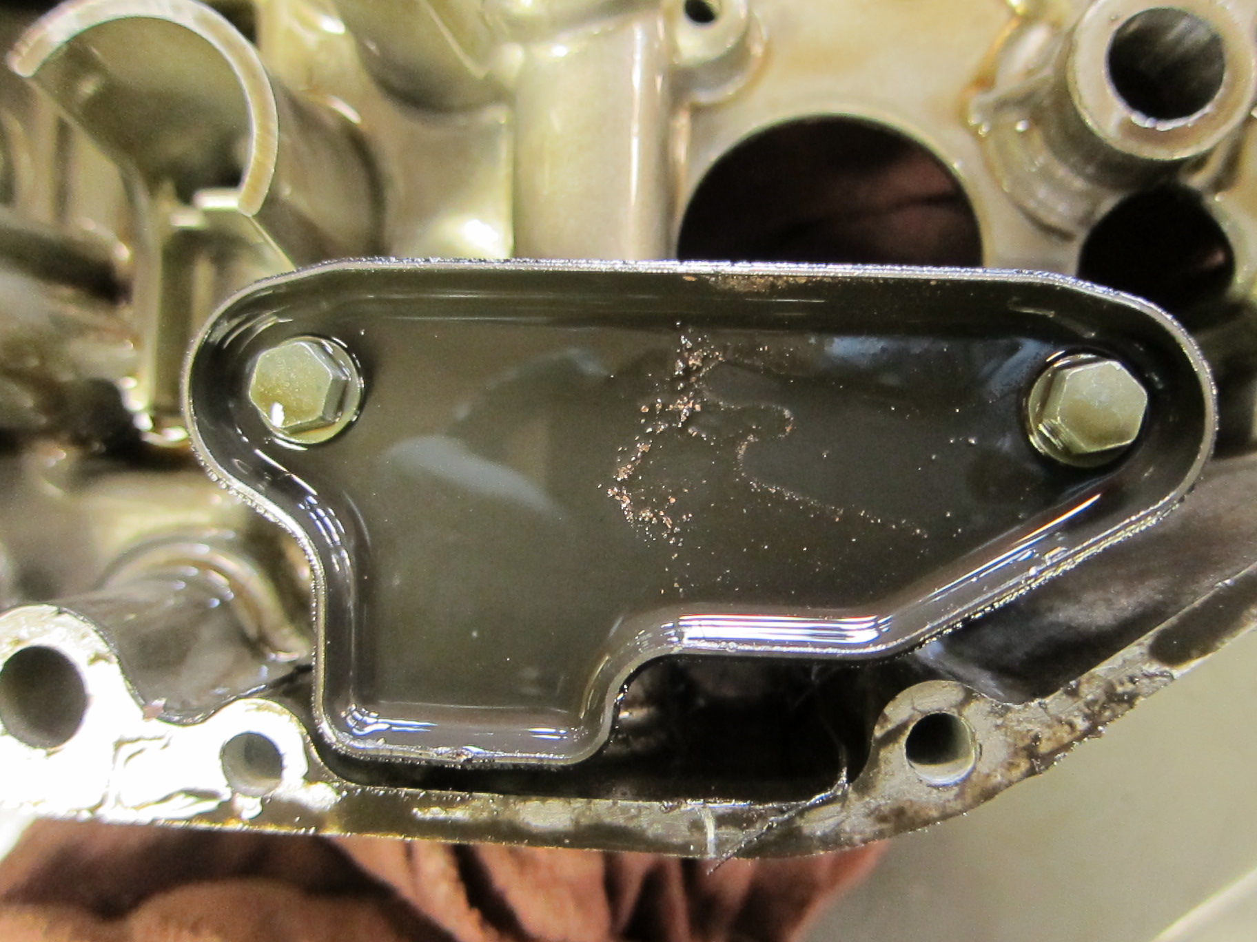
At this point, I began to see sparkly bits of metal deposited on the lower surfaces of the engine–a sure sign of severe lower-end engine damage. Those sparkly bits of metal were torn and sheared off something important…

Look carefully--metal particles are adhering to the lower surfaces of the engine

Something exploded into glittery fragments, leaving the residue here.
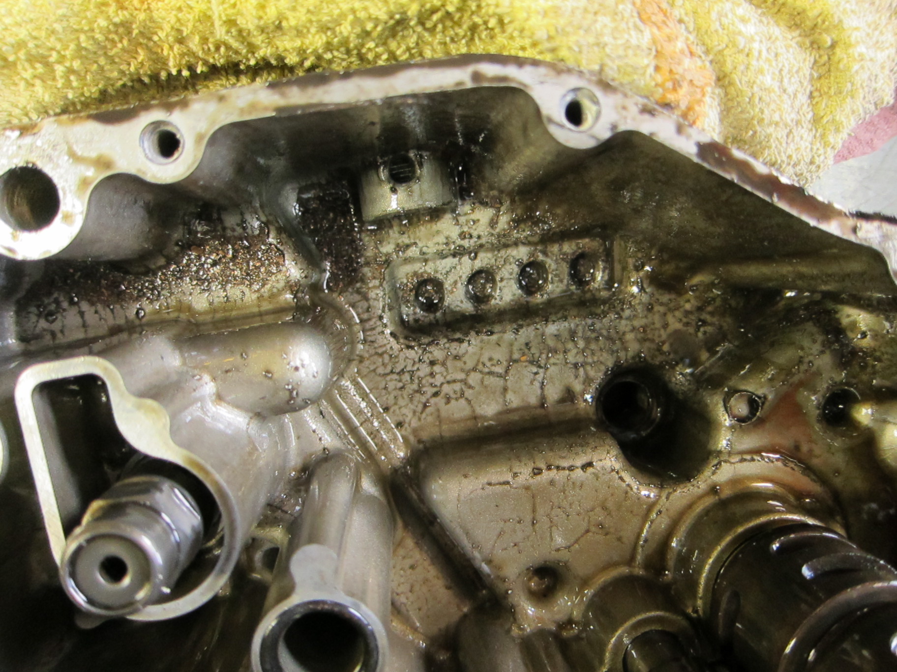
More "sparklies," metal shavings adhering to the bottom end of the engine. They're the result of destruction somewhere in the engine, and the scoring I found earlier was not enough to make this mess.

When the crankshaft came free, the connecting rods (which connect the pistons to the crankshaft) were heat-blackened, showing that they had endured tremendous overheating and abuse.
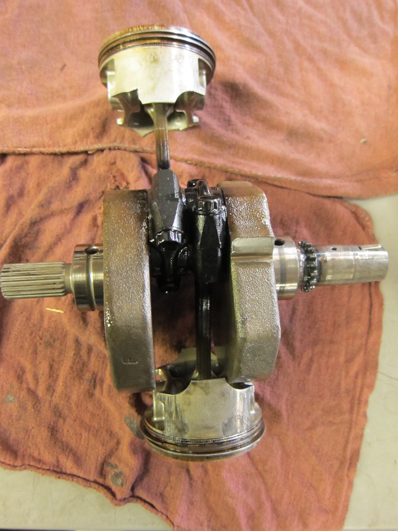
Crankshaft and pistons--note heat blackening on the lower sections of the connecting rods, where they bolt onto the crankshaft

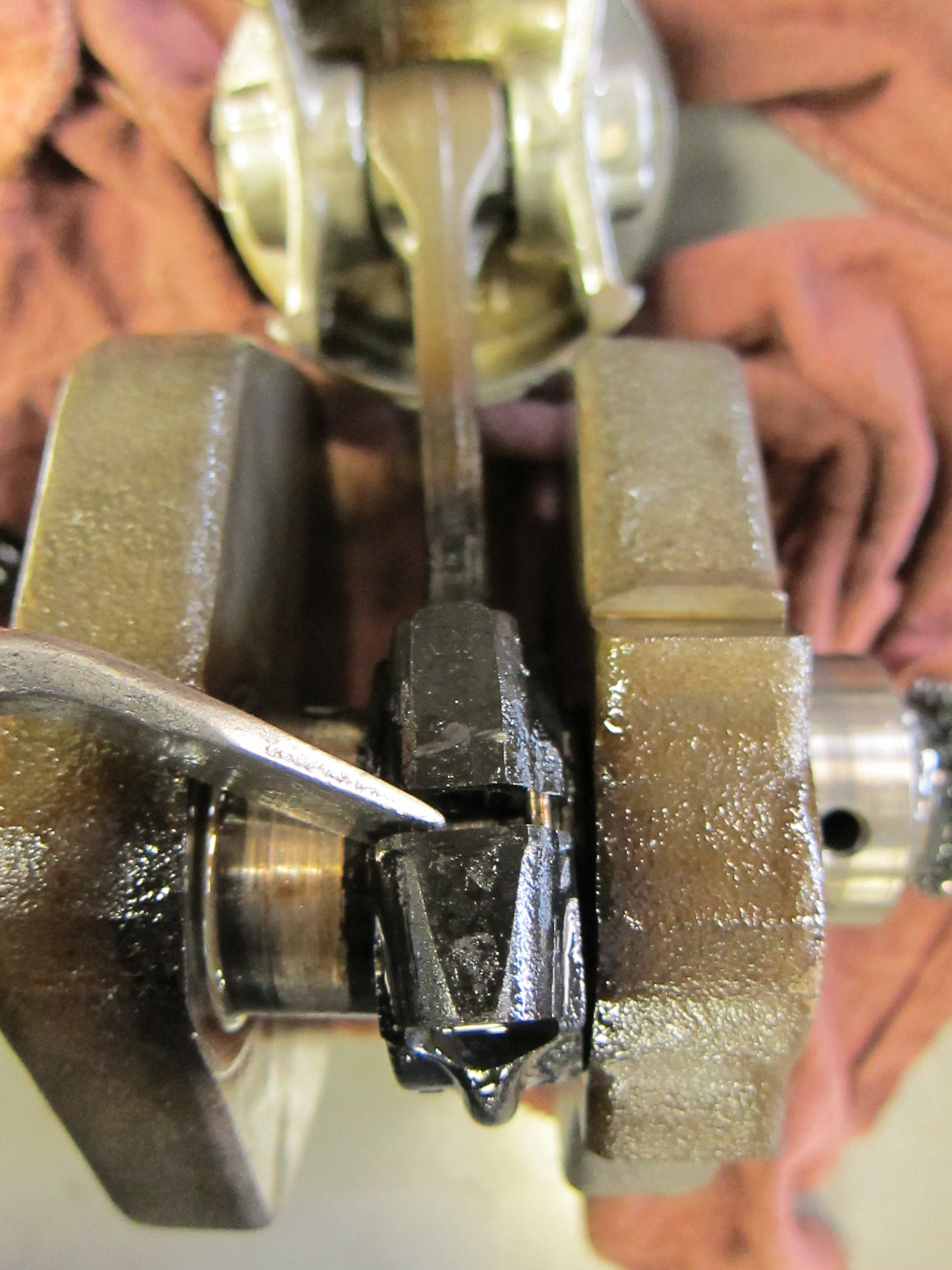
I turned over the crankshaft and unbolted the connecting rods.

End of the connecting rod, with bolts removed

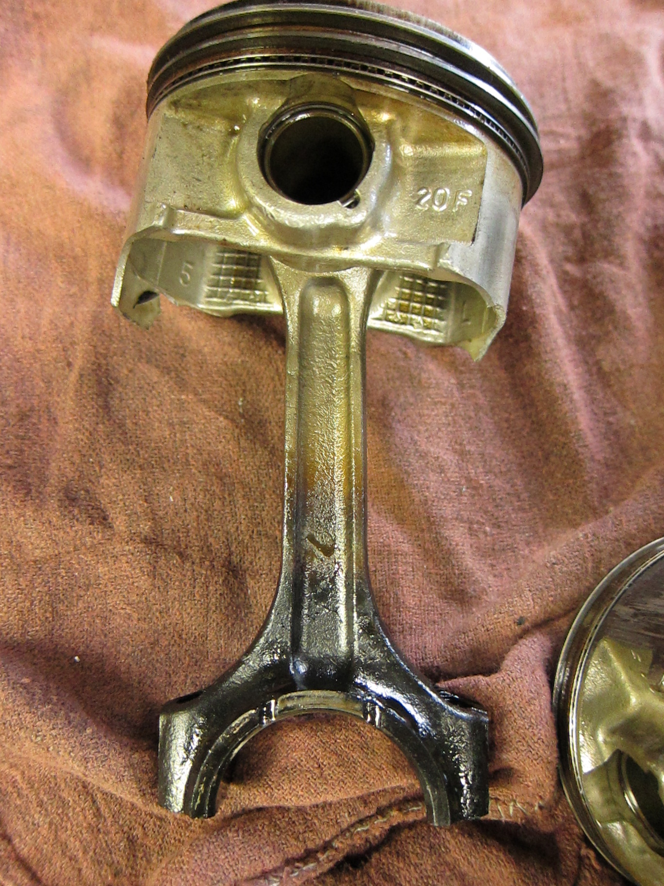
One of the con rods was just beginning to melt together (and the the crankshaft), and had to be pried apart with considerable force. It was another clue to the nature of the problem.

Connecting rod and piston

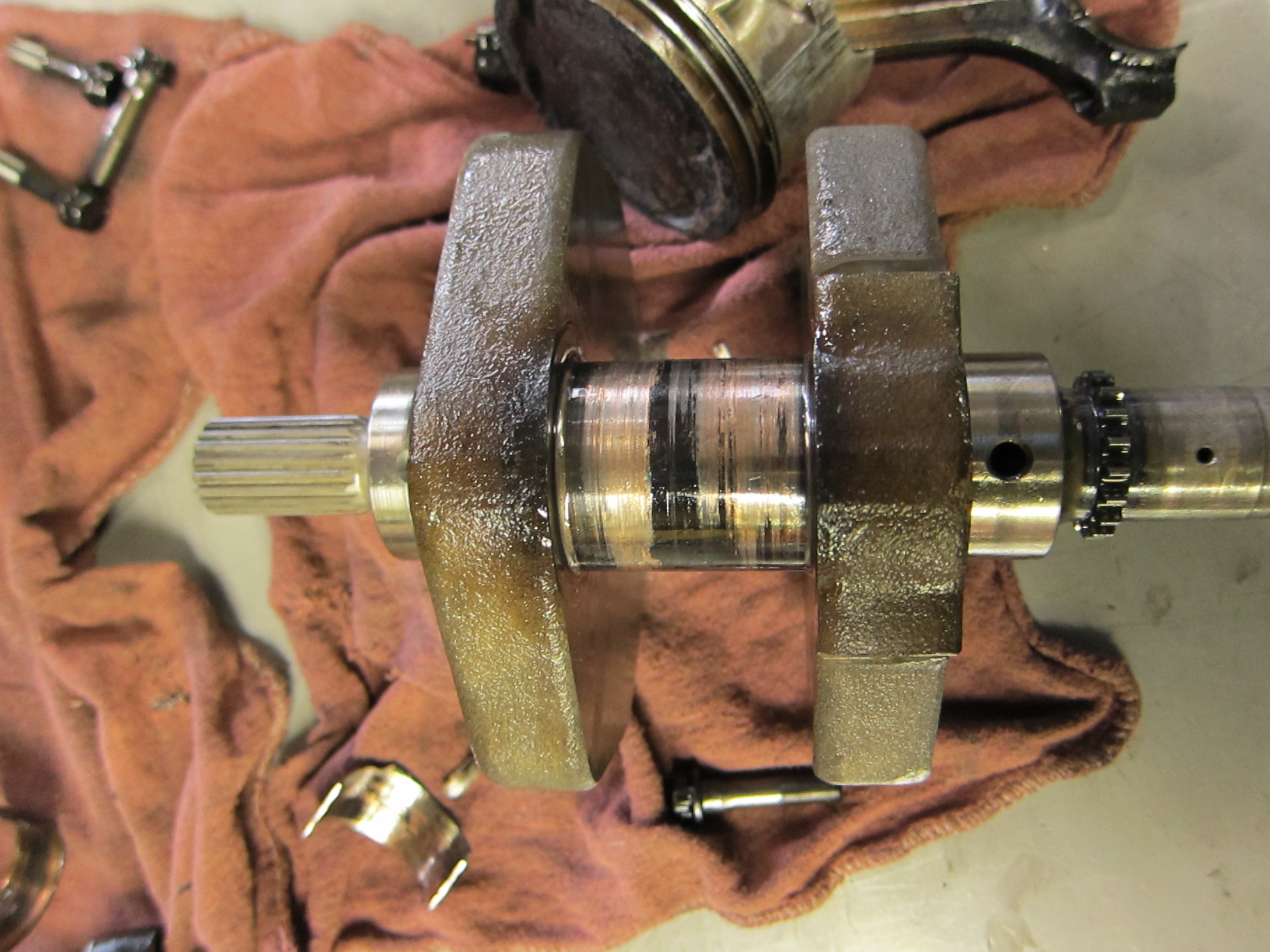
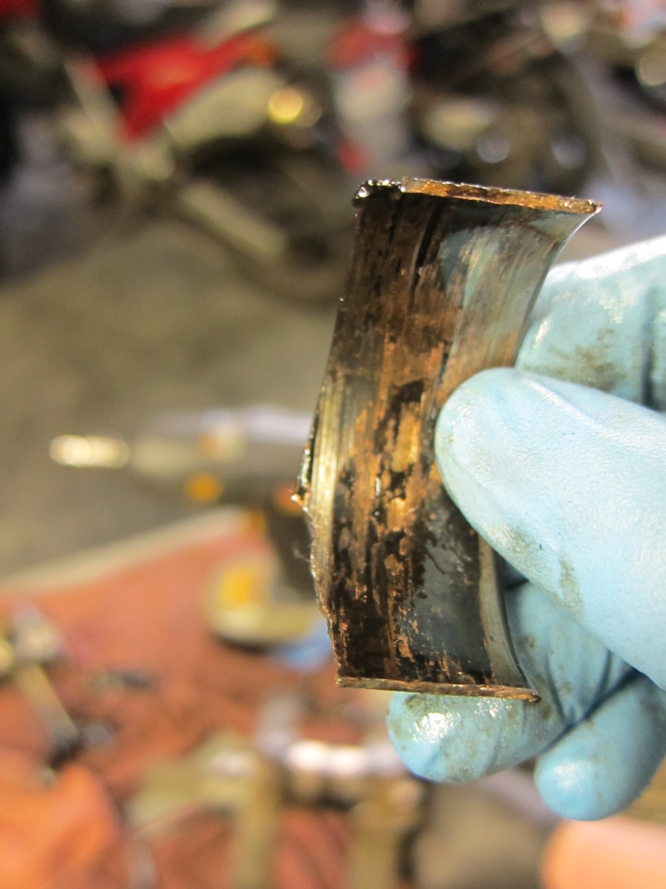
And when I finally pried off and set aside the pistons and connecting rods, down in the very belly of the beast, the oil-starvation problem suddenly revealed itself. The connecting rod bearings, which glide between the inner surface of each connecting rod and the outer surface of the crankshaft as it spins, had finally lost its protective coating of oil, and began to spin and melt and disintegrate. The scoring can be clearly seen.

Connecting rod bearings--scored and melted and damaged.

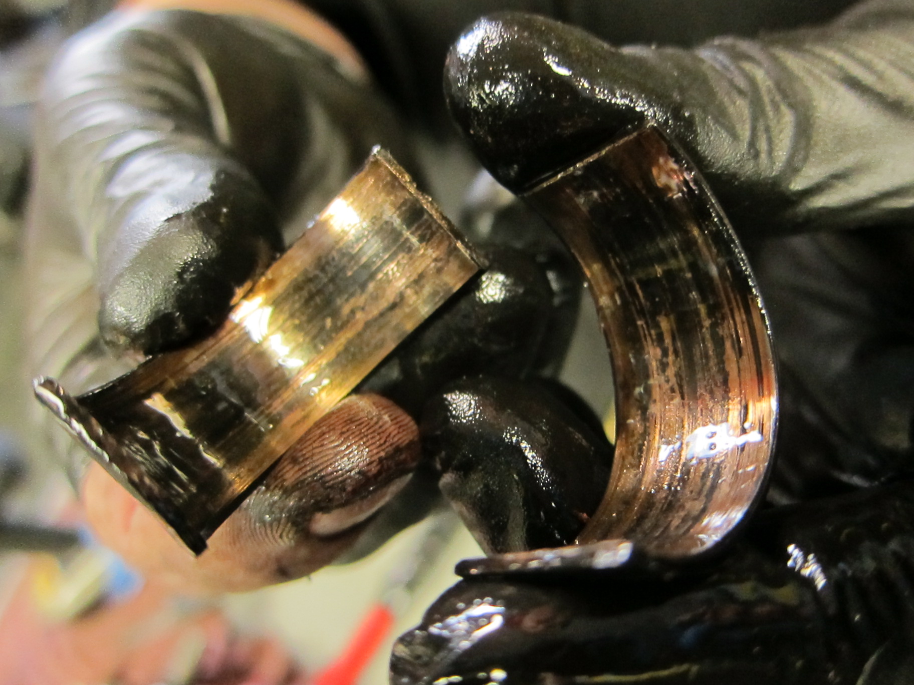
This was the source of all those metal flakes in the lower portions of the engine–the con-rod bearings shredding themselves into oblivion. I pried off the remains of the damaged bearings and took a closer look.

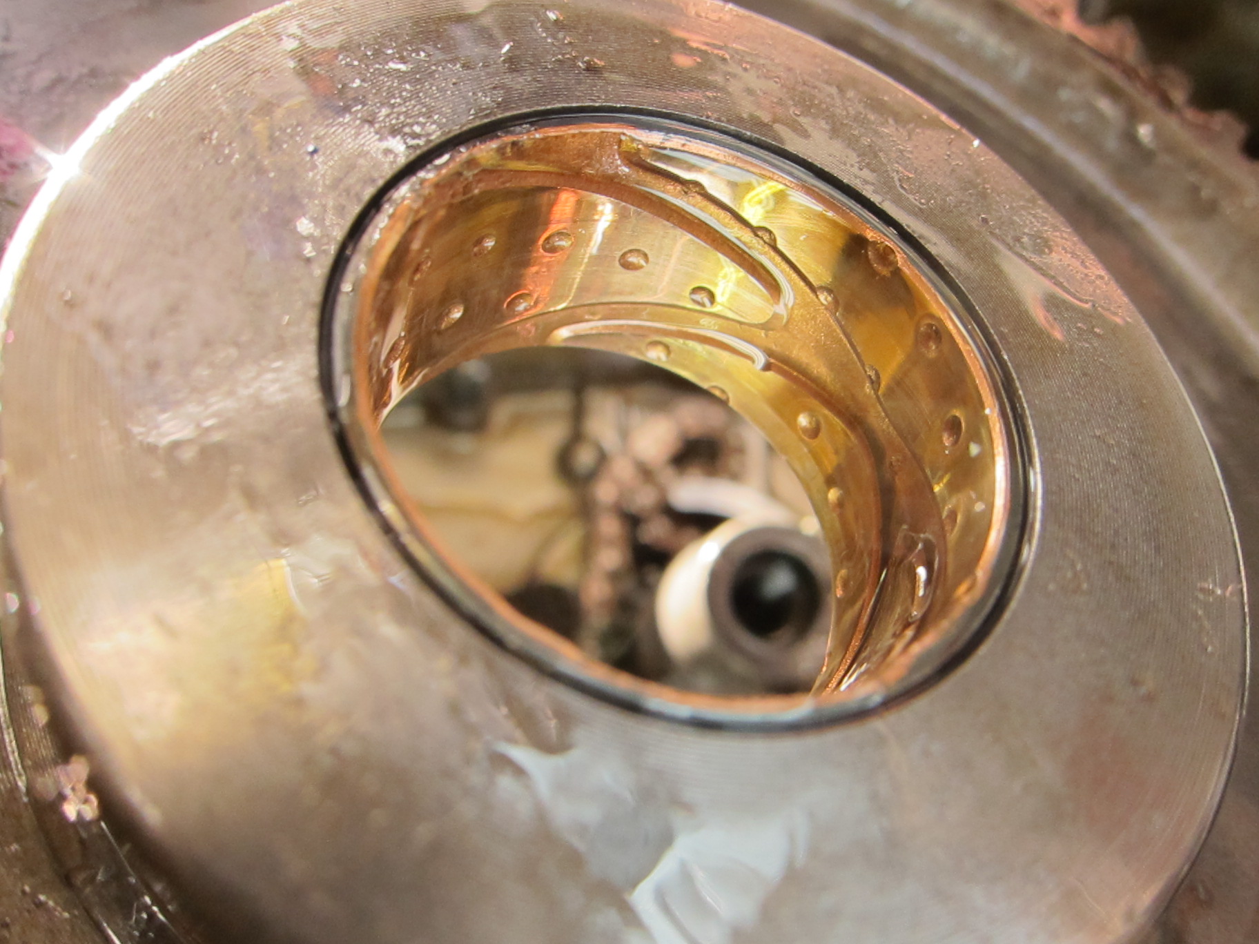
Inner surface of a heavily damaged connecting rod bearing--a classic example of a "spun bearing"

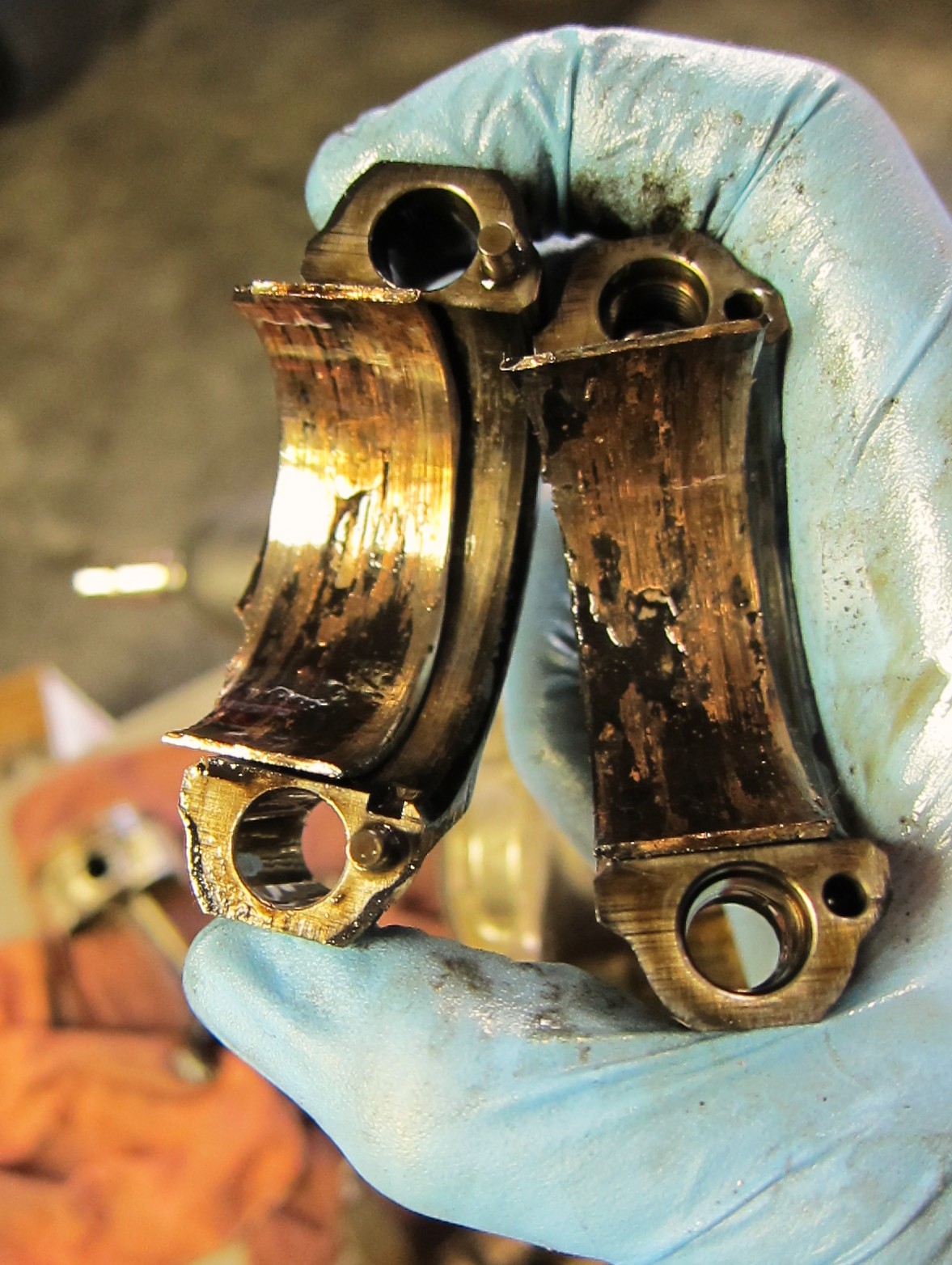
The truth was in there, and it was ugly.

Connecting rods with damaged bearings inside

Cause of death: spun bearings

So here before us was the verdict: in addition to the scored piston and cylinder, the doomed V-Strom engine died from a textbook case of spun con-rod bearings. It was a sad death, and a preventable one, but it was a fascinating learning process to deconstruct and diagnose the cause of the engine’s demise.

Remember, oil is the lifeblood of your bike’s engine!

Maybe that Pennsylvania groundhog is right

Ok. We’re not exactly breaking out the barbecue here on the North Coast of California.
Because it’s February. On the North Coast.
But it is warm, with temperatures flirting near the upper 60s. So warm that I fired up the bike this weekend and made a savage run to the beach, heating up the tires and getting a few grins while avoiding Sunday drivers and the fine gentlemen parked behind billboards.

Winter on the coast -- Highway 1 near Tomales Bay


Overall, it was a hell of a good day! My helmet is off to Punxatawney Phil. It was positively springlike.
Other riders took advantage, as well.
In my blast to Pt. Reyes Station via Highway 1, I saw sport bikes, dual sports and choppers, all basking in their own moto moments. I

No dog days of winter here

met a guy on a ’38 BMW R-61 who rode to Marin County from San Francisco wearing what looked like a trench coat.
He seemed surprised when I asked if he rode “that” over the Golden Gate Bridge.
“Of course I did,” he said, pointing out that the bike survived World War II and was rescued from a Polish barn. “Why wouldn’t I?”
He rolled away in a whir of sewing machine noise.
I took it as my cue and got my modern-day bike up to warp speed, flying north up the asphalt ribbon that envelopes Tomales Bay.
I scraped a foot peg or two, paused for pics and headed back to may own barn.
I stopped short of reconnecting the trickle charger. I have a feeling I won’t be needing it.

–BV

Engine Autopsy 1–What Happens When a Bike is Starved for Oil?

Recently, several riders have brought oil-starved bikes into the shop–whether they were new riders or simply neglected to check their oil level for too long, the results have been uniformly disastrous. Motorcycle engines tend to rev high and hot, and like other internal combustion machines, an engine’s metal-to-metal contact points need a consistent film of oil lubrication between moving parts, whether those parts are bearings, camshafts, or piston and cylinder. When the oil level drops below a certain level, it spells certain doom for the bike’s motor–possibly with terrible consequences for the rider. In this case, the V-Strom’s owner ignored the low oil light for approximately 2,000 miles before the bike “began to make a terrible rattling noise” and breathed its last. The unmistakable rattling noise and the sparkling bits of metal in the oil confirmed to us that the motor was in bad shape. Turned out that the engine was damaged beyond repair; we found a replacement engine and installed it, and the rider learned an expensive lesson in responsible bike maintenance.

Riders–remember to check your oil level and keep your bike filled to the appropriate level! The engine is the heart of a bike, and oil is its lifeblood.

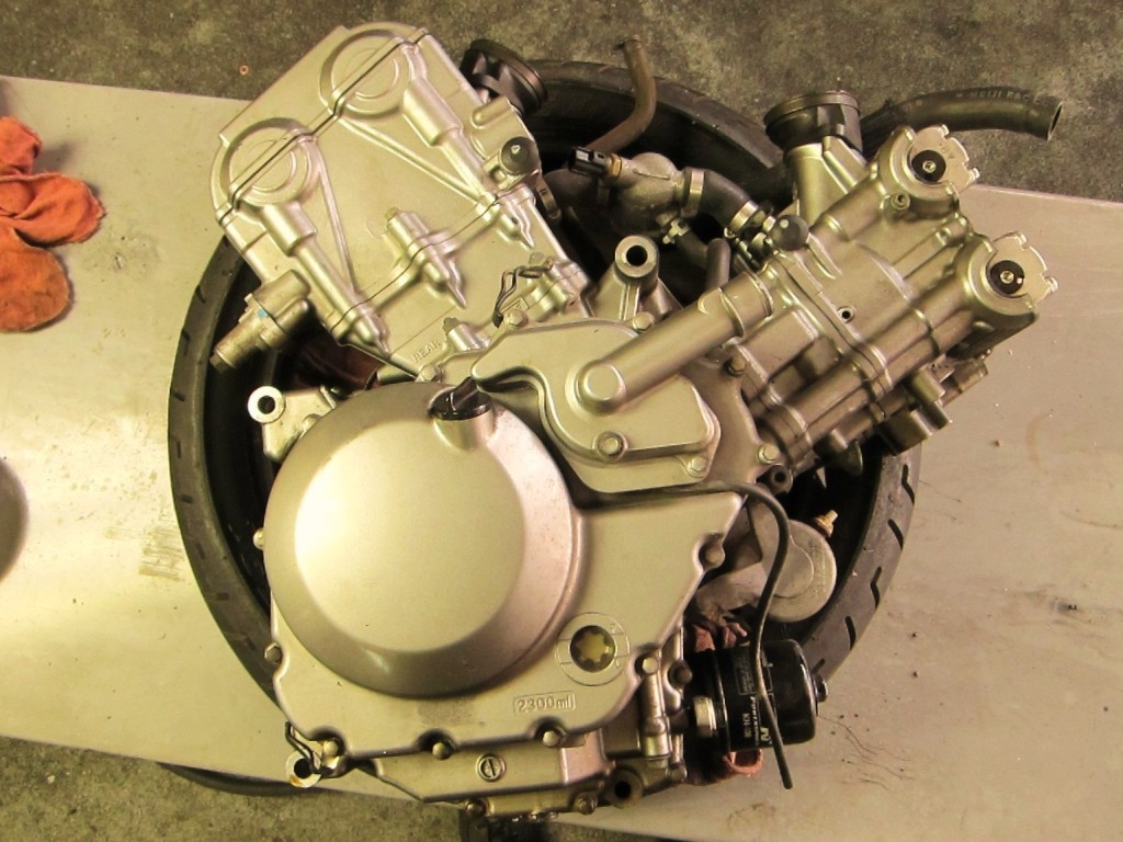
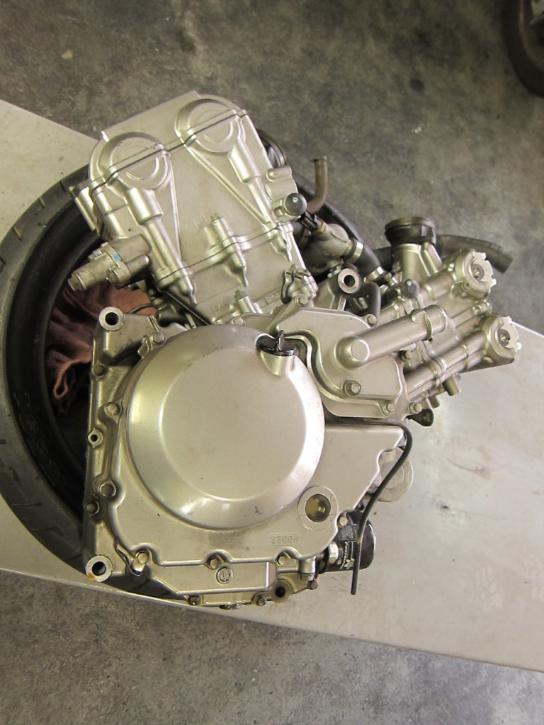
The engine from a 2007 Suzuki V-Strom 650--the same bike featured in the oil change tutorial This one, however, was ridden by its uninformed owner until it was dry of oil

Another view of the V-Strom engine--note that the front cylinder has already had its valve cap removed in an effort to diagnose the problem.

It’s painful but fascinating to dig into a ruined engine like this and do a sort of autopsy to discover which parts failed. This is the normally very robust vee-twin engine on the lift, ready for disassembly. It’s a messy, dirty job, so I’ve got gloves on and plenty of rags and a pan on hand to catch spills.

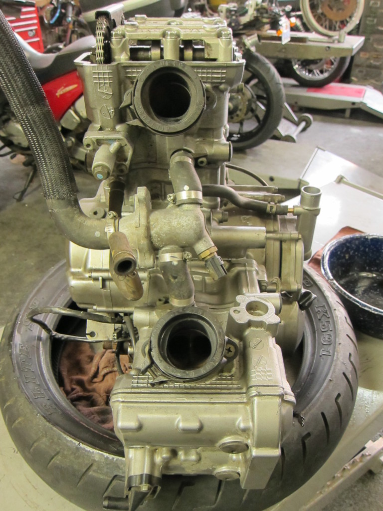
Vee-twin top view, with water pump and coolant hoses intact

First I loosened the bolts and eased out the starter motor.

Out comes the starter motor

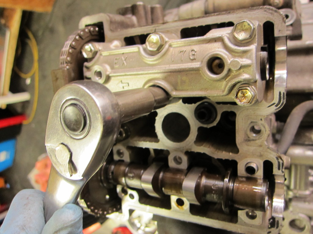
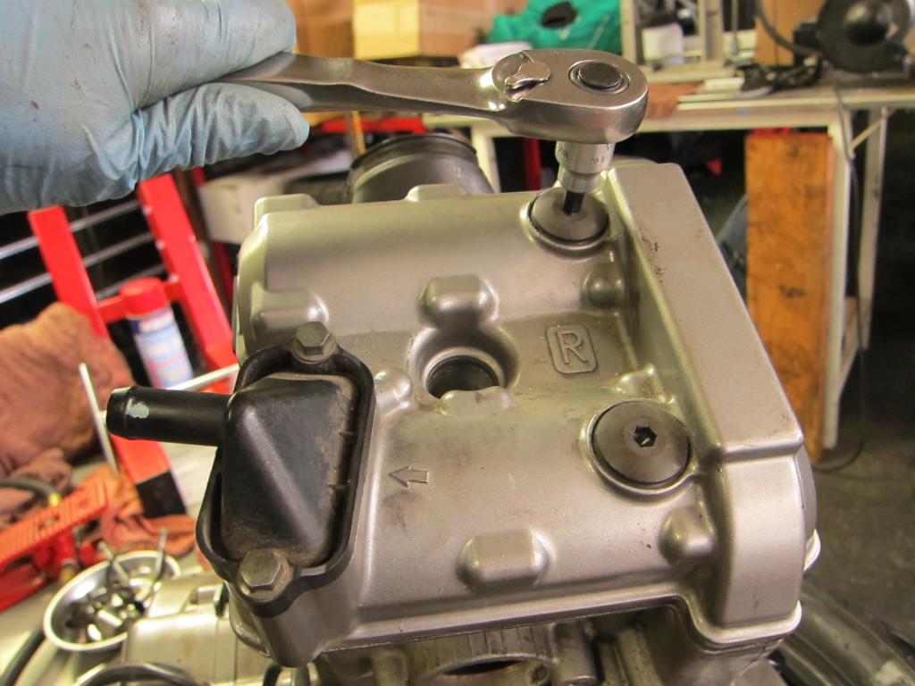
Next, off came the valve cap on the forward cylinder head, and then I removed the camshaft journal covers. In both cases, the caps should be removed in a star pattern to prevent the aluminum from warping as it is removed.

Removing the camshaft covers

In order to loosen the cam chain and remove the camshafts, the cam chain tensioner needs to come off first.

Removing the cam chain tensioner

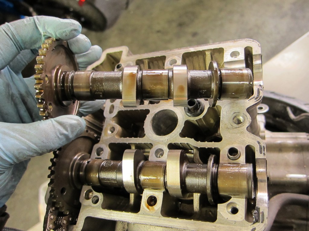
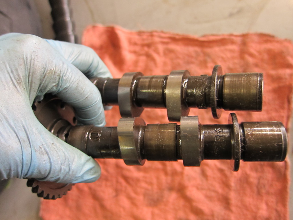
At this point, the camshafts are exposed, and the cam chain is loose and can be pulled off, releasing the camshafts. The cam lobes, which rotate and push the valves open and closed, are vulnerable when the bike’s oil runs dry, as are the camshaft journals, which turn inside their bearings in the engine head. Upon inspection, though, the entire surface of both the intake and exhaust camshafts showed no evidence of wear or galling, a testament to the toughness of the V-Strom engine.

Pulling and inspecting camshafts

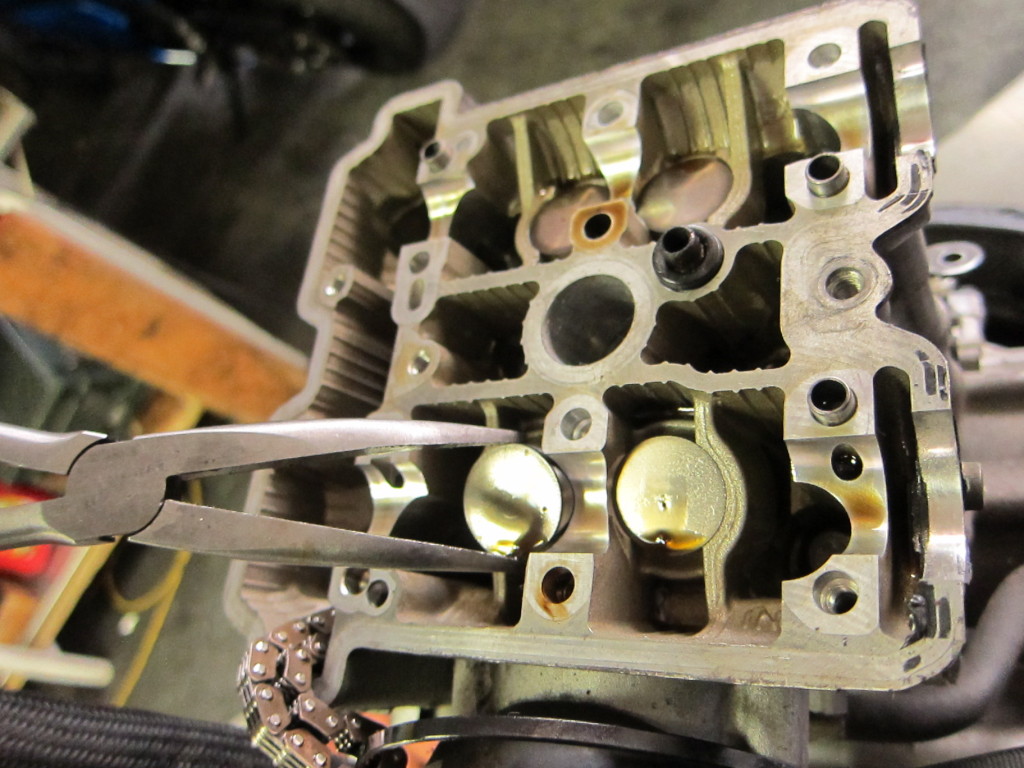
With the camshafts removed, the valve tappets (or buckets) are exposed, easy to pull with a pair of needlenose pliers or a magnet. Since the V-Strom uses a shim-under-bucket valve design, each shim sits on the underside of each tappet. The small shims require care and a deft hand to avoid dropping into the engine, a bad scene if you’re doing a valve adjustment.

Pulling valve tappets

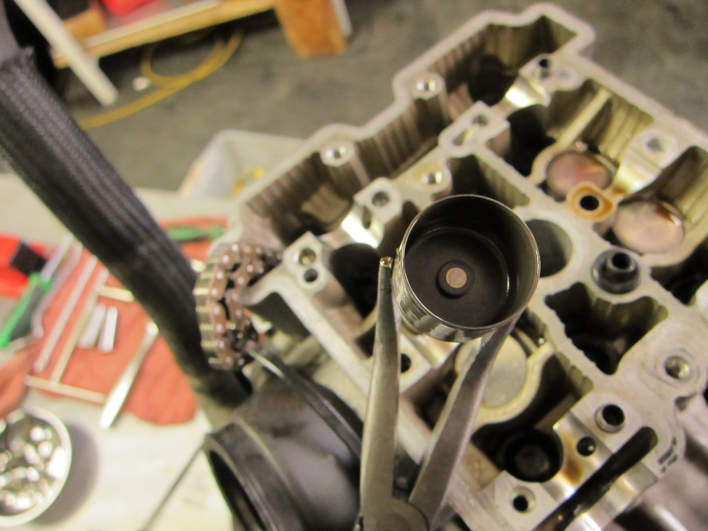
Generally, as here, the small shim adheres to the underside of its tappet, and comes out with it.

Shim, stuck under under its bucket with a thin film of oil

With the camshafts, tappets and shims gone, the valve ends and the tops of the valve springs can be seen.

The four valve ends and springs

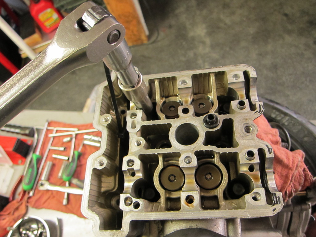
The head bolts came out next–that took a breaker bar.

Using a breaker bar to remove the head bolts

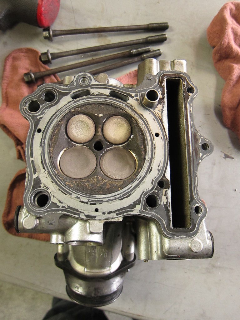
The intake and exhaust valves showed no obvious signs of being bent, a frequent result of oil starvation.

Underside of the head, showing intake and exhaust valves

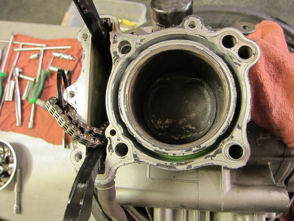
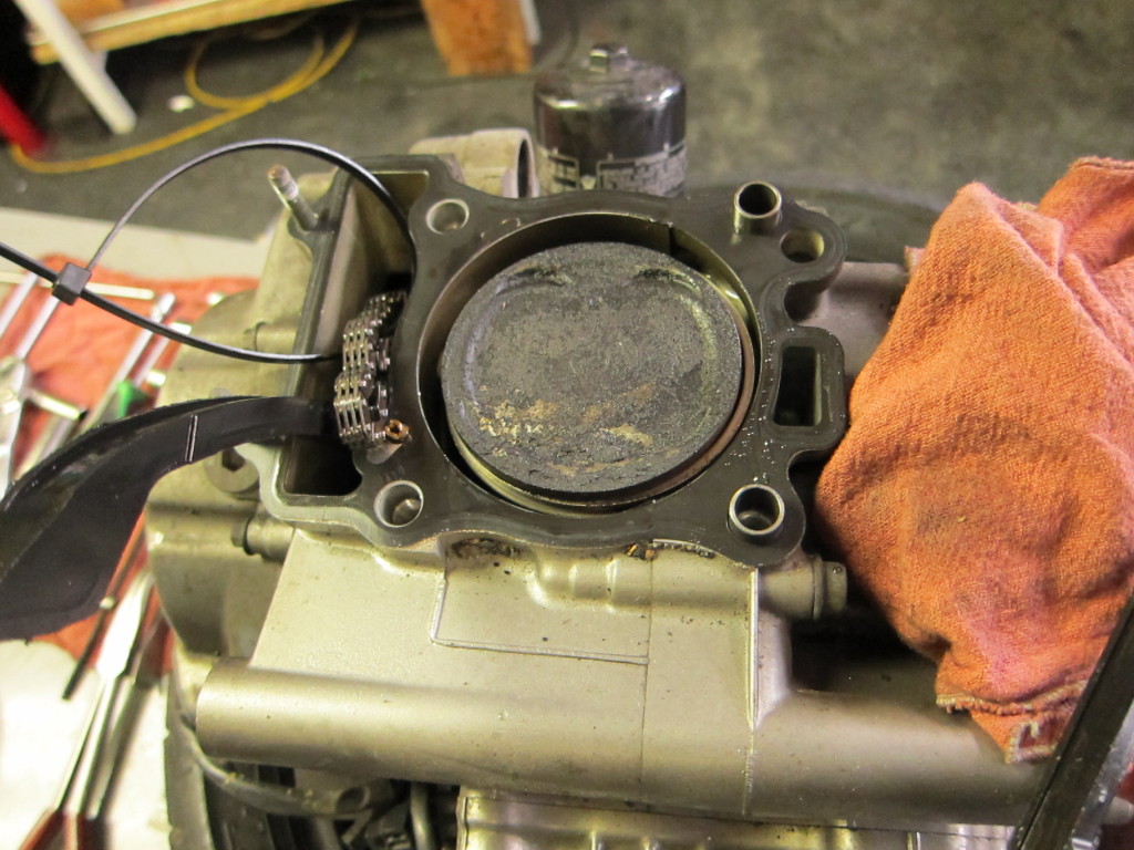
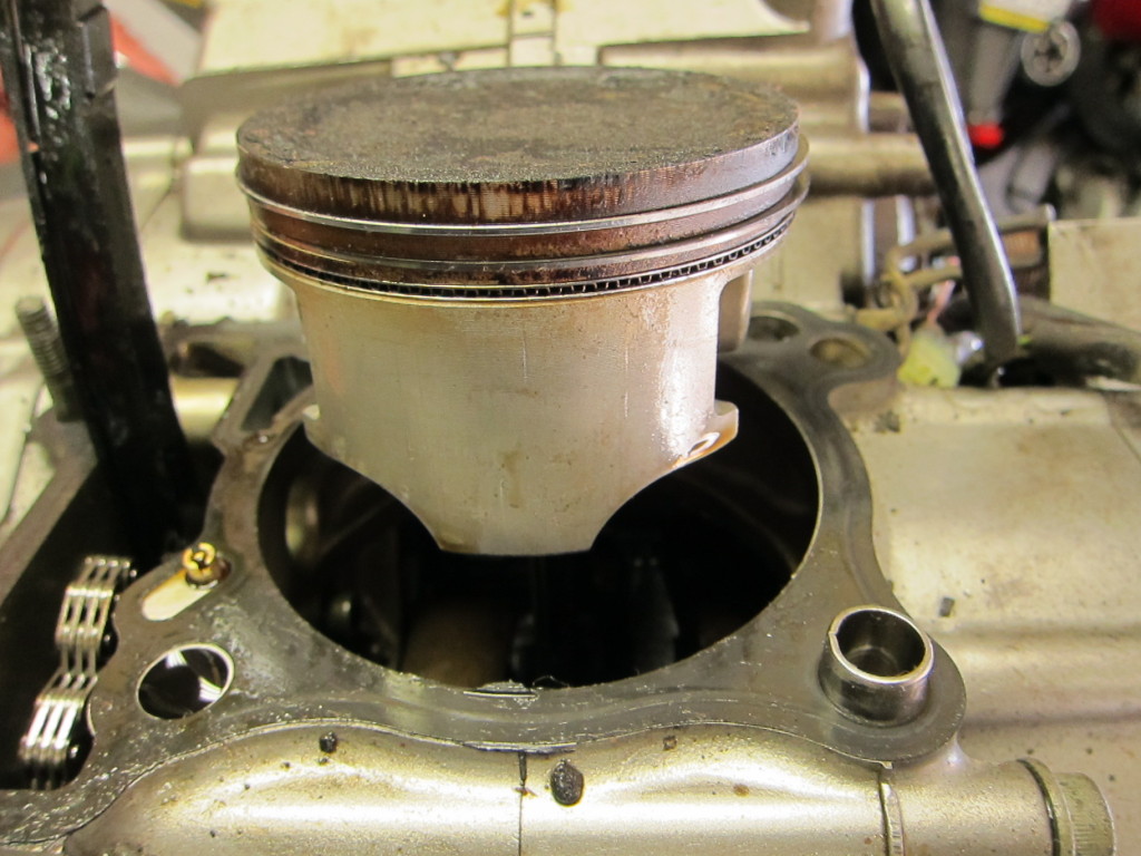
Now that the head was off, the cylinder and piston face were visible.

Cylinder and piston face

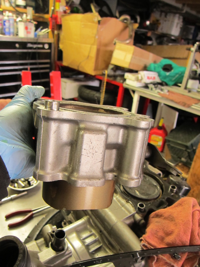
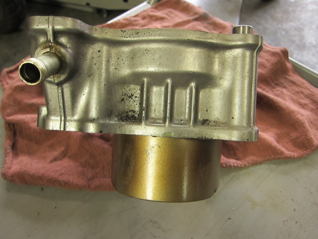
With the head bolts out, I was able to pull and inspect the cylinder.

Jug and cylinder

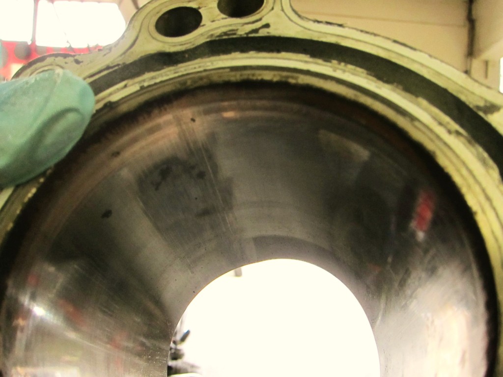
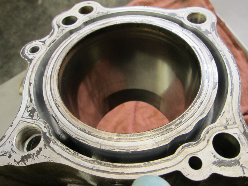
The interior of the cylinder shows some scoring.

Scored interior of the cylinder

Normally, the piston rides up and down the cylinder in a thin film of oil. But when the oil is gone, there’s direct metal-to-metal contact as the piston begins to scrape and gouge the cylinder–and you can see the results.

Cylinder scoring

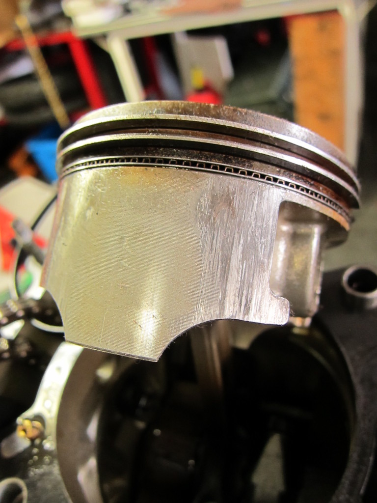
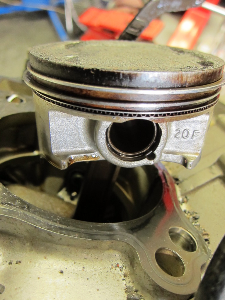
The piston skirt had signs of scoring beginning to show as well. If the engine had not been shut off when it was, the gouges would have deepened in both the metal of the cylinder and the piston, eventually breaking one or both, or melting them together and seizing the engine.

Scored piston

More piston damage

I repeated the process with the other cylinder.

Rear cylinder cap removal

Second piston face

Cylinder #2 removed

Rear cylinder looks less damaged than the front cylinder

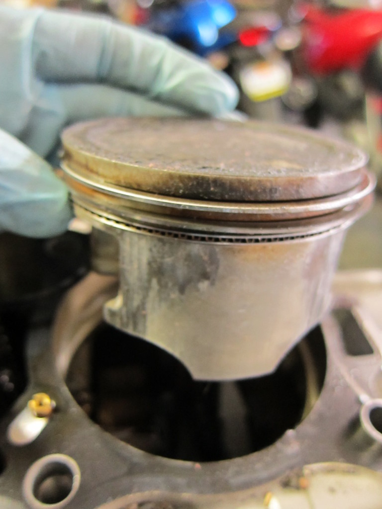
This piston, too, showed little to no damage, unlike the front cylinder’s piston.

This piston looks relatively ok

Another view of the piston

The two rear cylinder camshafts were in fine shape, as well.

Rear cylinder camshafts, undamaged

After the cylinders were removed, the stator cover was next.

Stator Cover

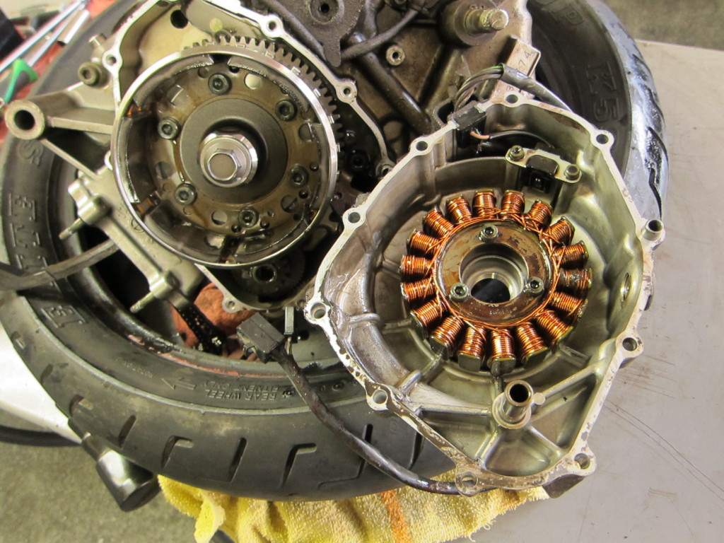
With a bit of convincing with the deadblow hammer, the stator cover and stator came away, resisting as the flywheel magnets attempted to hold the stator in place.

Stator cover, pulled, showing stator coils on right and flywheel on left

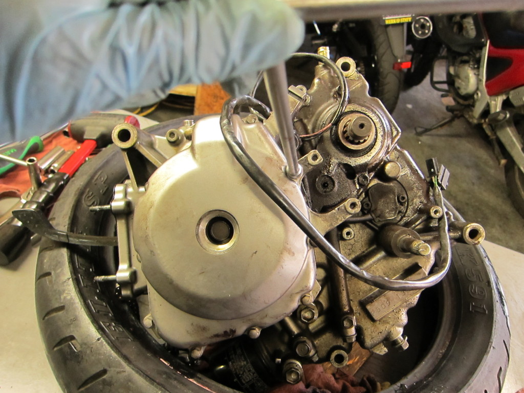
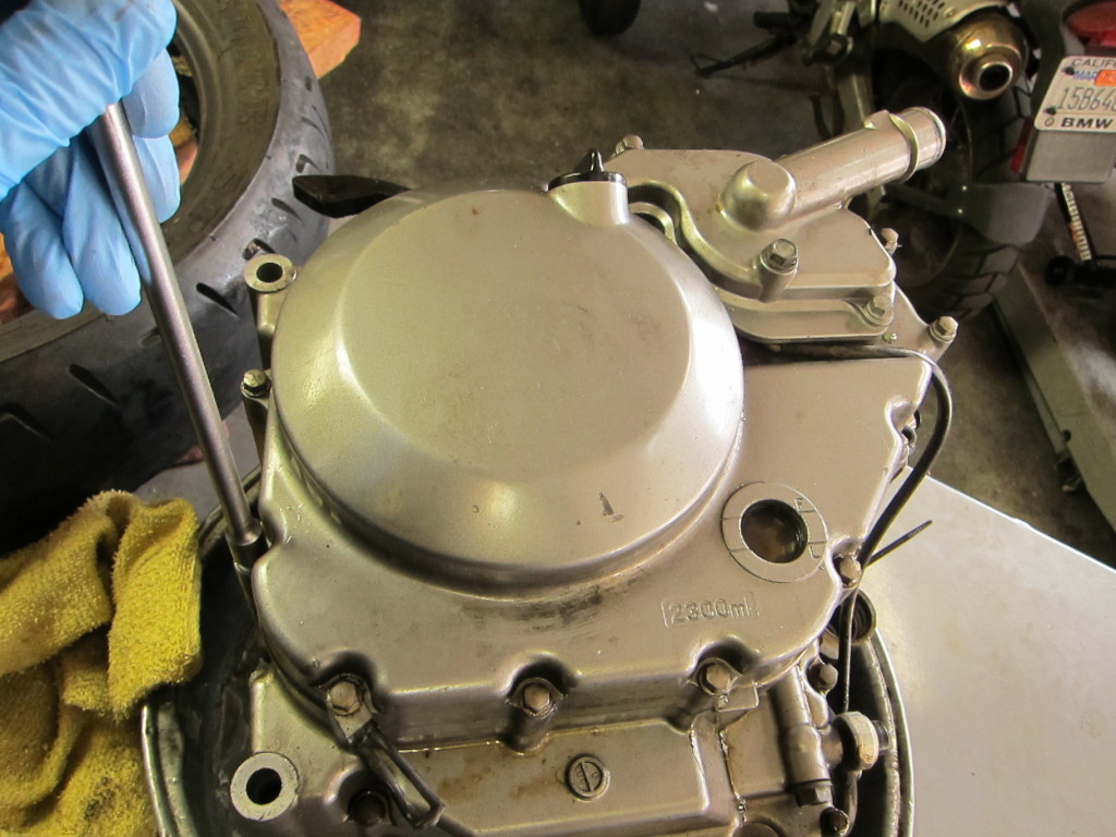
With the stator cover off, I flipped the engine over to take off the clutch cover on the other side.

Clutch cover

The clutch cover came off more easily, showing the clutch basket beneath.

Clutch exposed

And next, I unbolted the clutch basket itself and removed it.

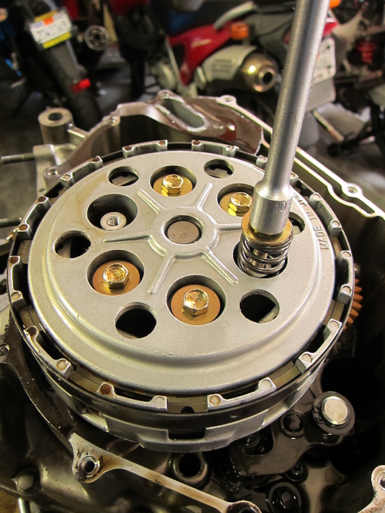
Removing the clutch springs to free the clutch basket

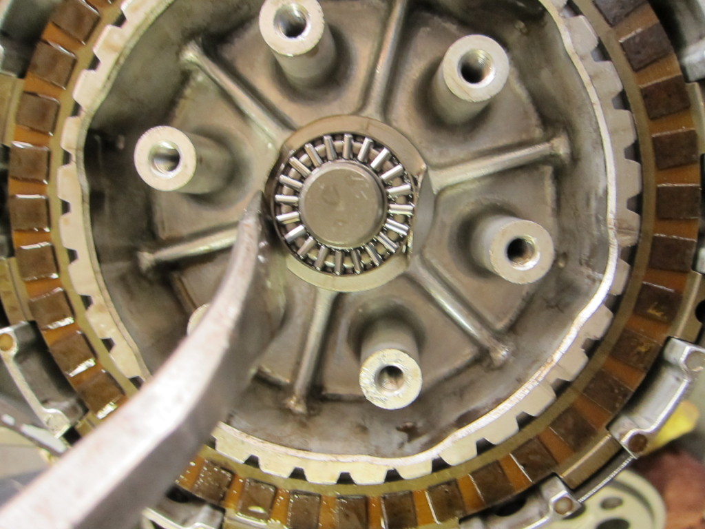
Now with the friction plates and steels out, the basket lay beneath. I pressed down the folded-up tabs of the washer holding the nut and friction bearing, and took them out.

Clutch plates out, and friction bearing exposed

With the clutch basket gone, the deeper parts of the crankcase are exposed (the plastic gear is the oil pump gear).

Beneath the clutch

With the top end of the engine (cylinders, valve head, camshafts and covers) apart, and the side covers, stator and clutch removed, it was time to get into the depths of the crankcases and see what damage had been wrought in the engine’s bottom end–which I’ll cover in the next post.