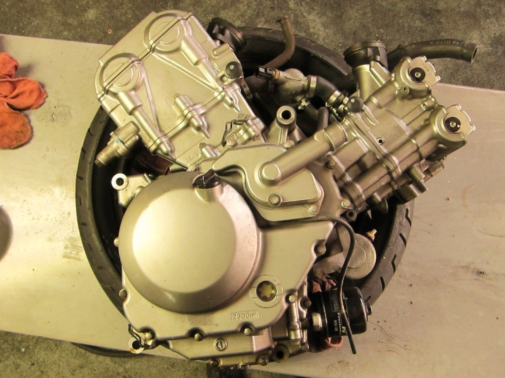
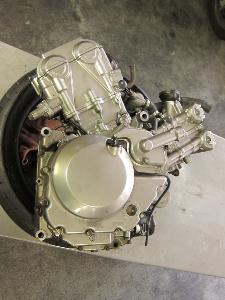
Our deconstruction of an oil-starved Suzuki V-Strom engine continues…
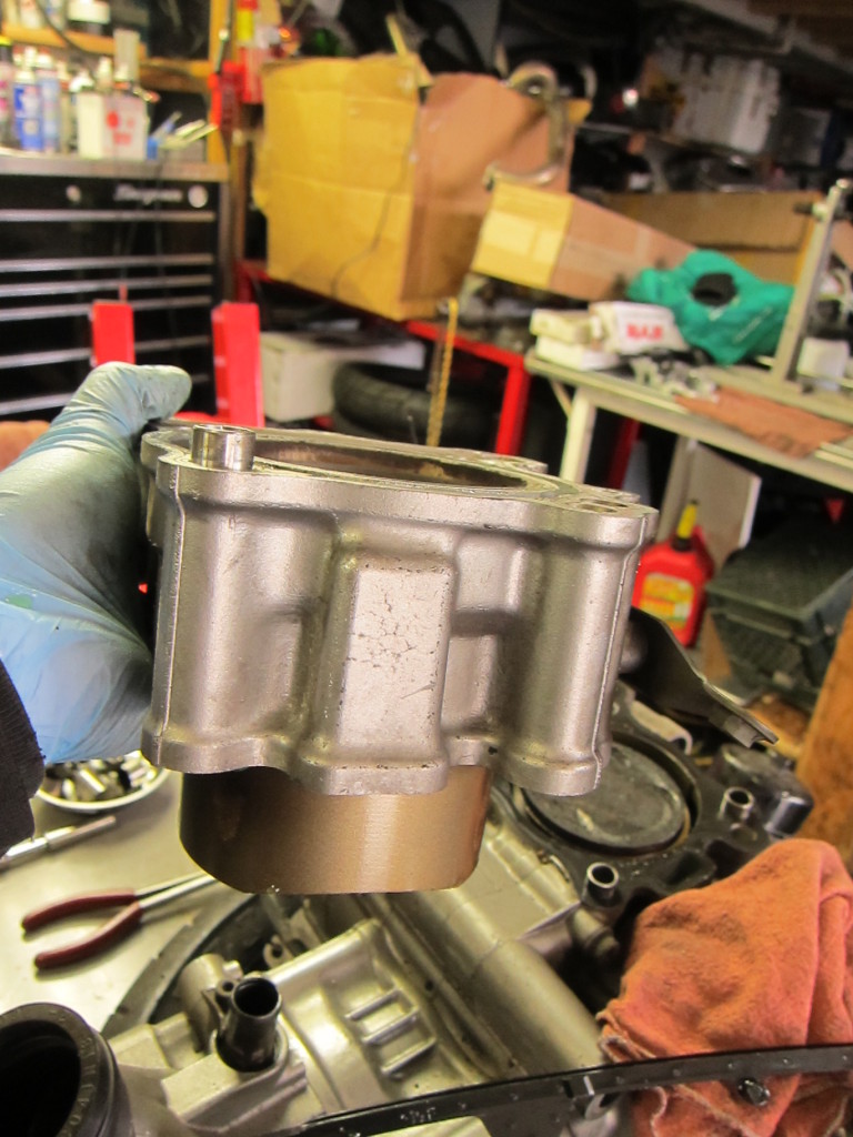
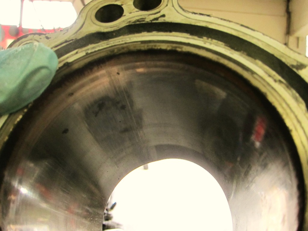
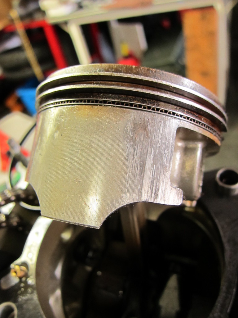
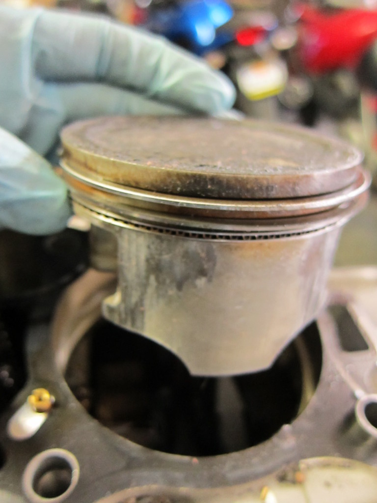
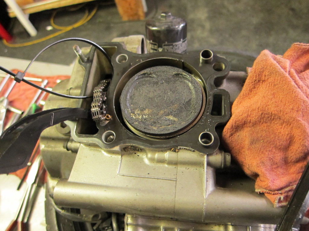
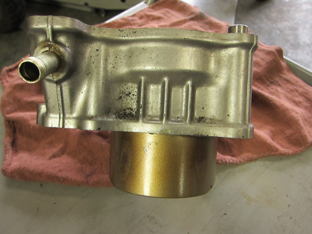
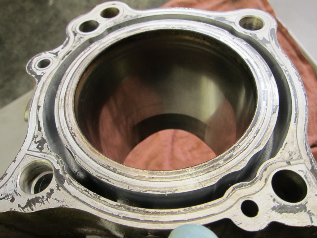
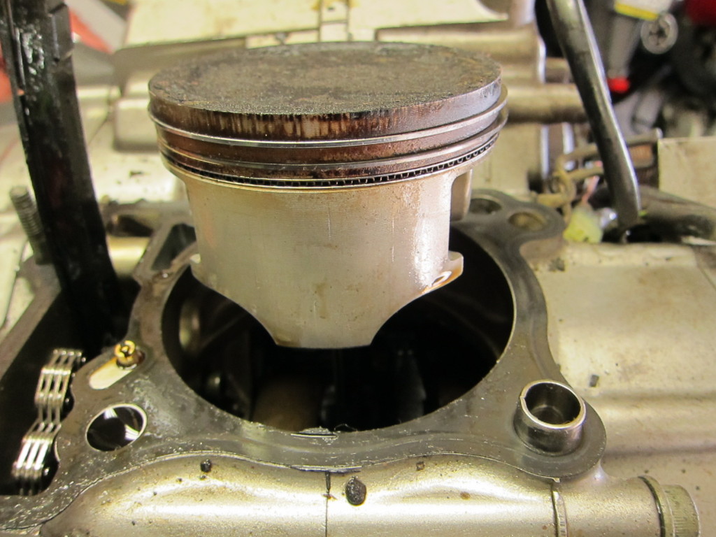
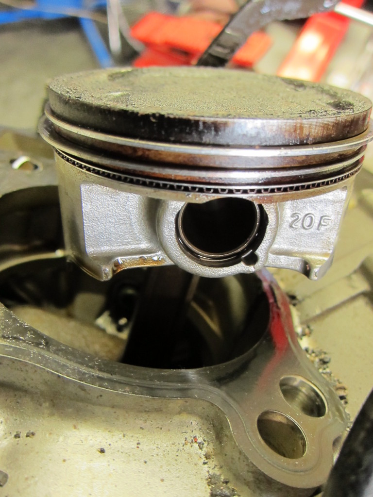
In the last post, I took apart the top end of the engine, finding some cylinder and piston scoring from running the engine dry. Now, to dig down even further into the mystery and find the bike’s exact cause of death.
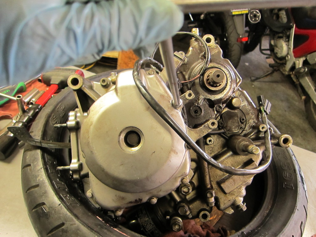
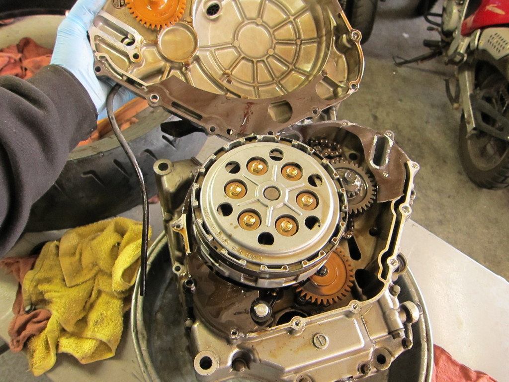
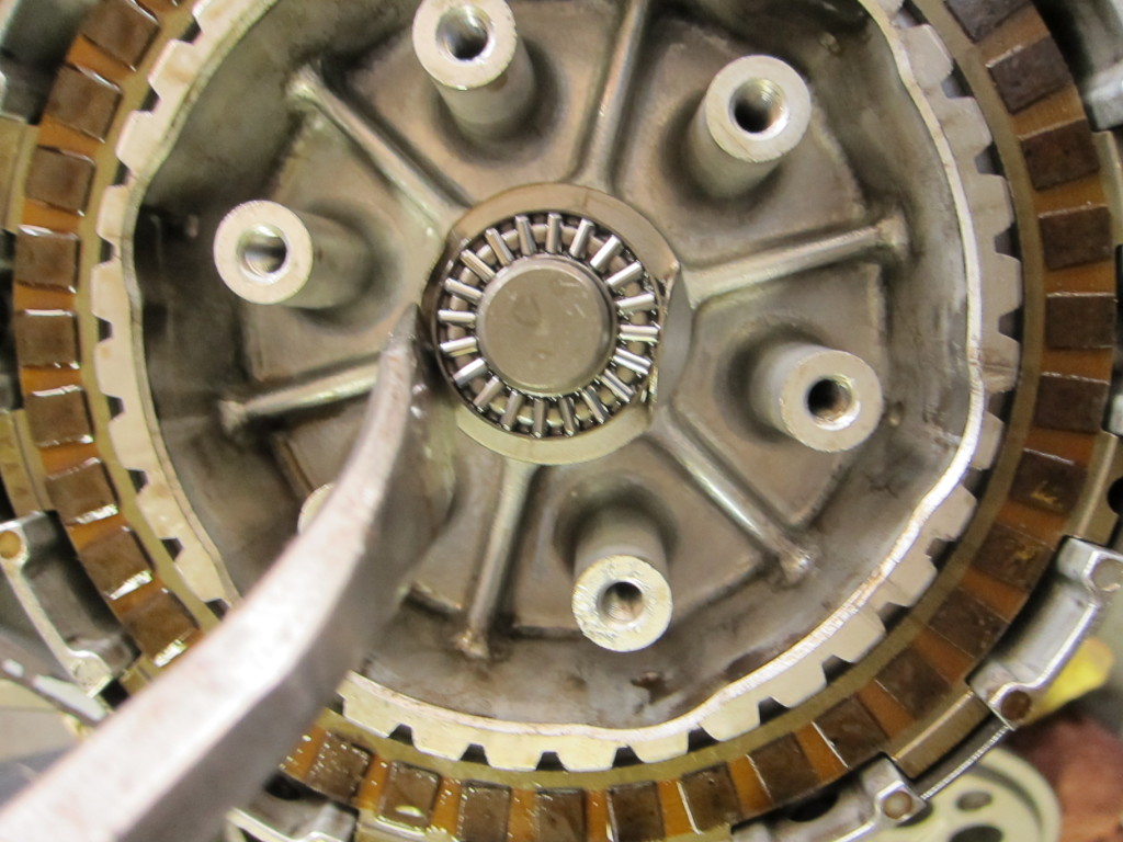
This was our last view last time; the clutch and basket were off, revealing the oil pump gear (orange), the drive shaft (top), and the lower cam chain sprocket (left).
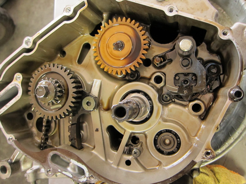
Grabbing the circlip pliers, I lifted off the circlip, then the oil pump gear.
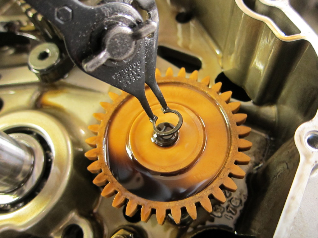
Oil pump gear, held on with circlip
The oil pump had a small transverse pin holding it in place below the oil pump gear. With it out of the way, the oil pump could be lifted out.

Oil pump, freed
The cam chain sprocket nut was reverse-threaded, and required some bearing down with the rattle gun before budging.
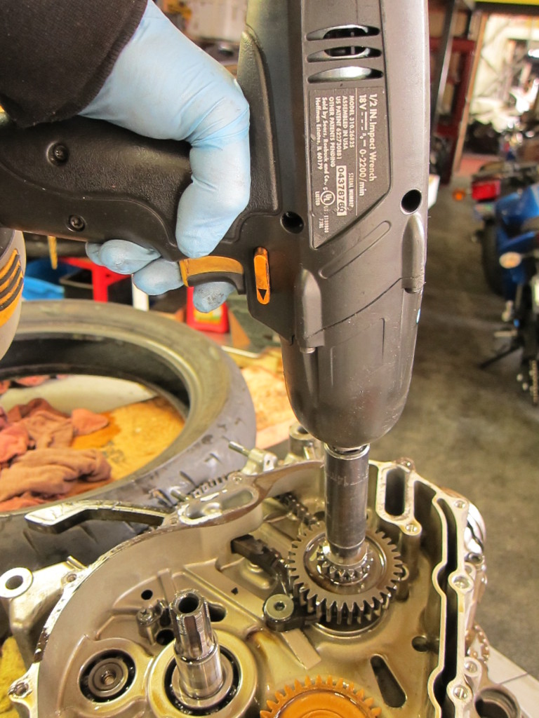
The nut holding on cam chain sprocket comes off with an impact gun
Next it was on to the gear shift plate, with the shift shaft running through the transmission below it.

Gear shift plate--Time to start dismantling the transmission
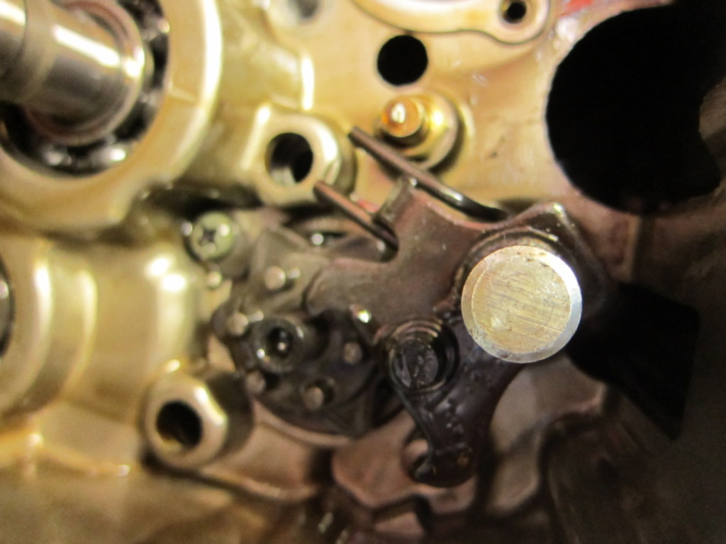
Beneath the gear shift plate
At that point, I was able to pull the shift shaft from the left side of the engine.
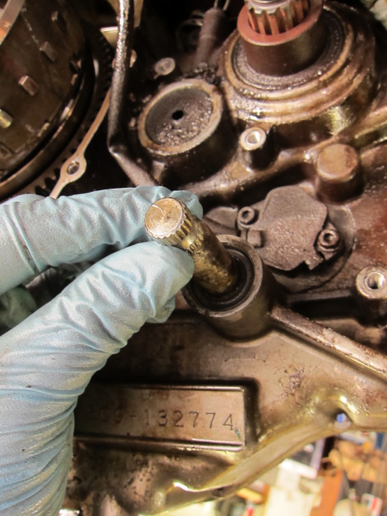
Pulling the shift shaft
After that was out, I began cracking loose the 8mm case bolts with my trusty T-handle.
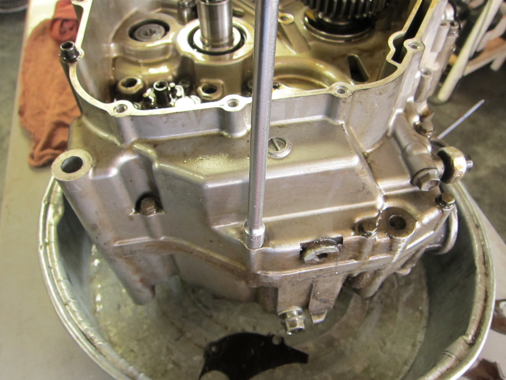
Beginning to work on the 8mm case bolts

Closer and closer to splitting the cases...
With some of the easily-accessible case bolts out, it was time to turn the motor over and remove the flywheel. The retaining bolt needed an impact gun to get loose.
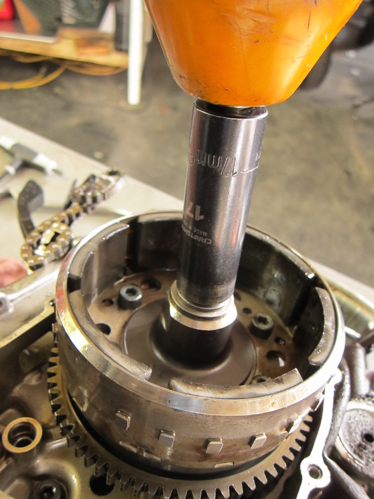
Flywheel bolt--more work for the trusty impact gun
With some effort, it came off. I moved on to the flywheel allen bolts.
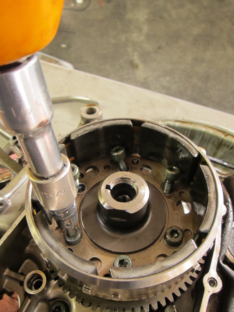
Removing the flywheel allen bolts
Fortunately the shop has a universal flywheel puller on hand; I threaded in the 22mm size end and prepared to do battle with the flywheel (also known as the rotor). It’s on there very tightly, and has magnets cast into it, so removing it is a memorably sweaty task.
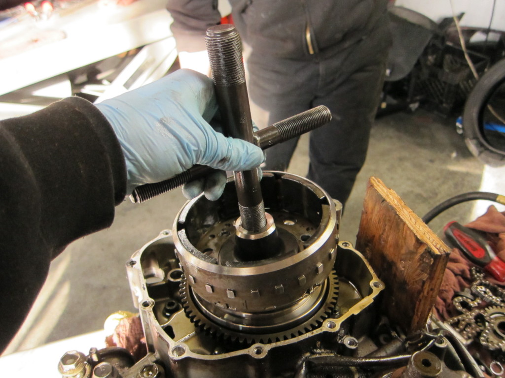
Threading in the flywheel puller
I hammered on that flywheel puller and flywheel with my skinny arms for a while, until the hammer flew out of my sweaty hands and nearly hit my coworker. At last, the flywheel came off with a mighty blow.
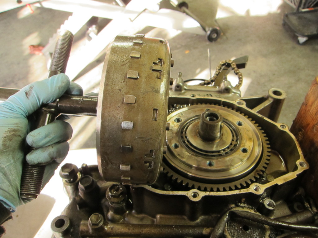
Victory! The detached flywheel
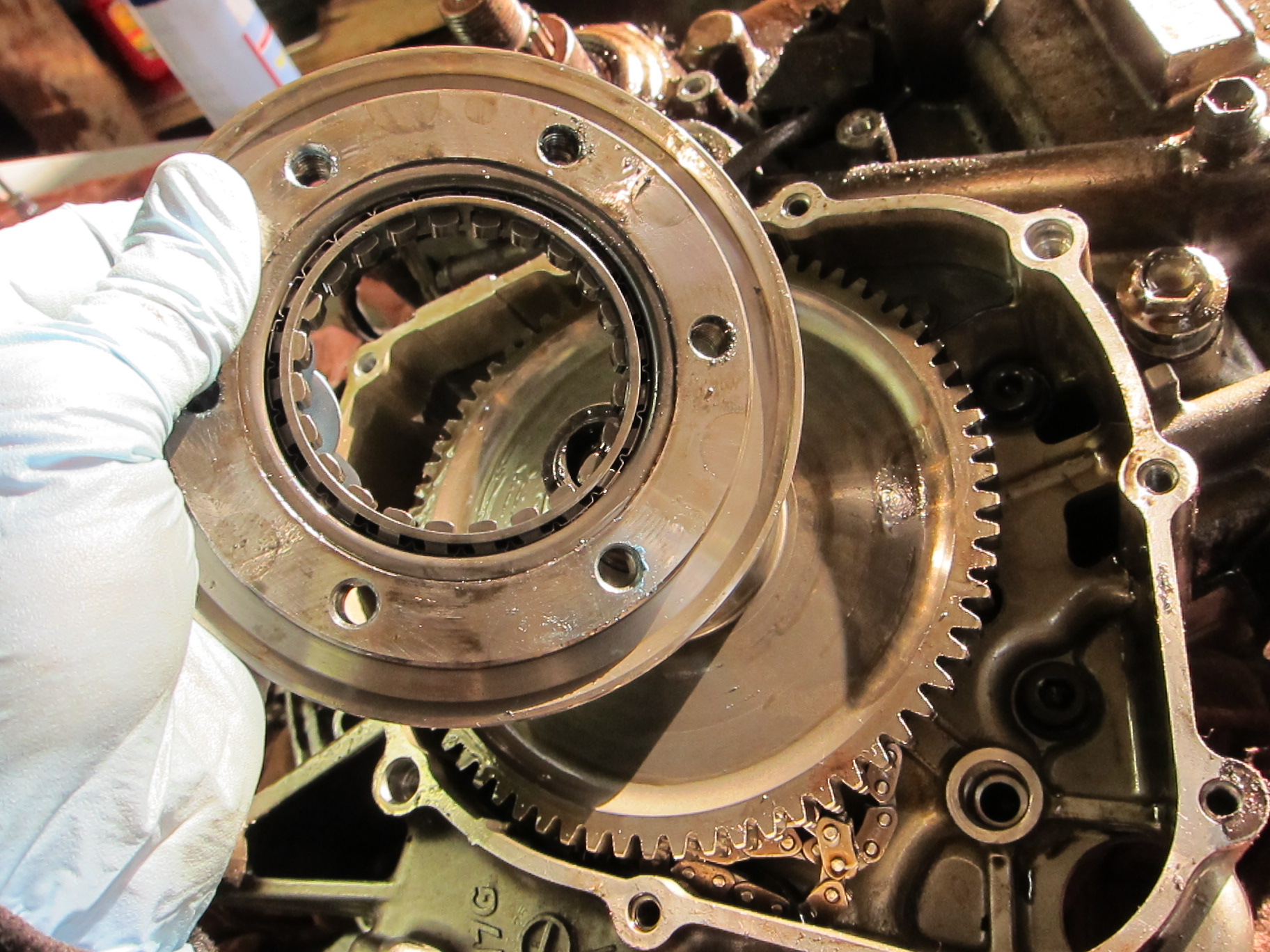
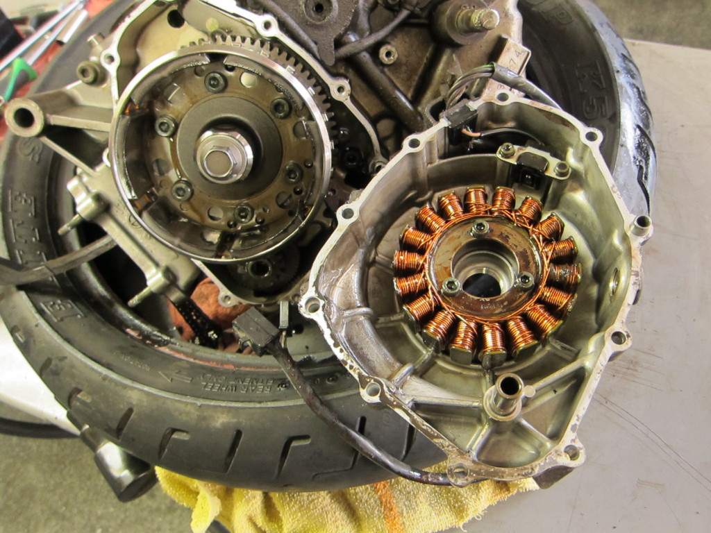
Removing plate and gears below the flywheel/rotor
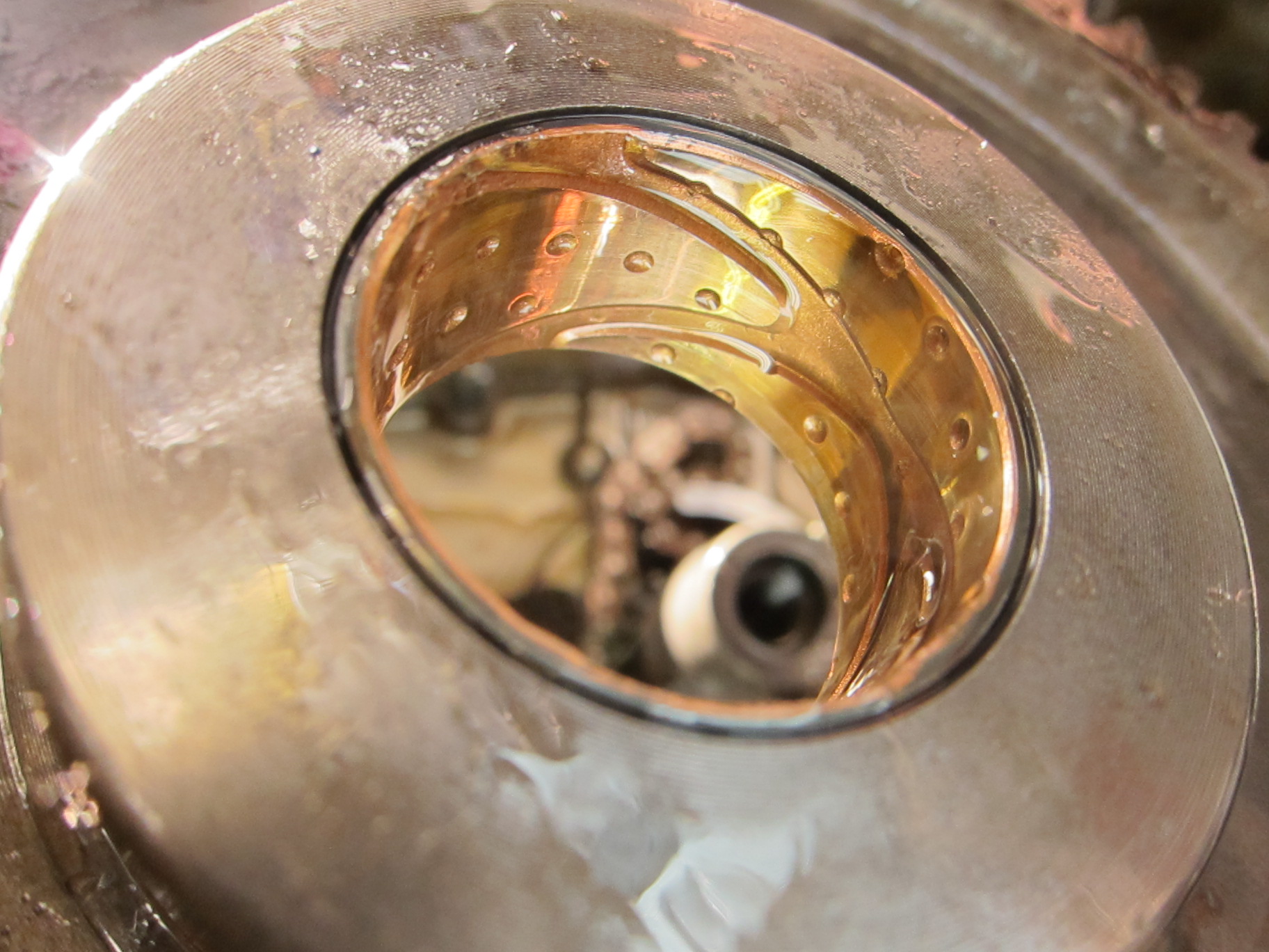
Fascinating slotted insert/worm gear insert beneath the flywheel
With the flywheel and supporting plate and gear gone, the drive shaft was exposed.
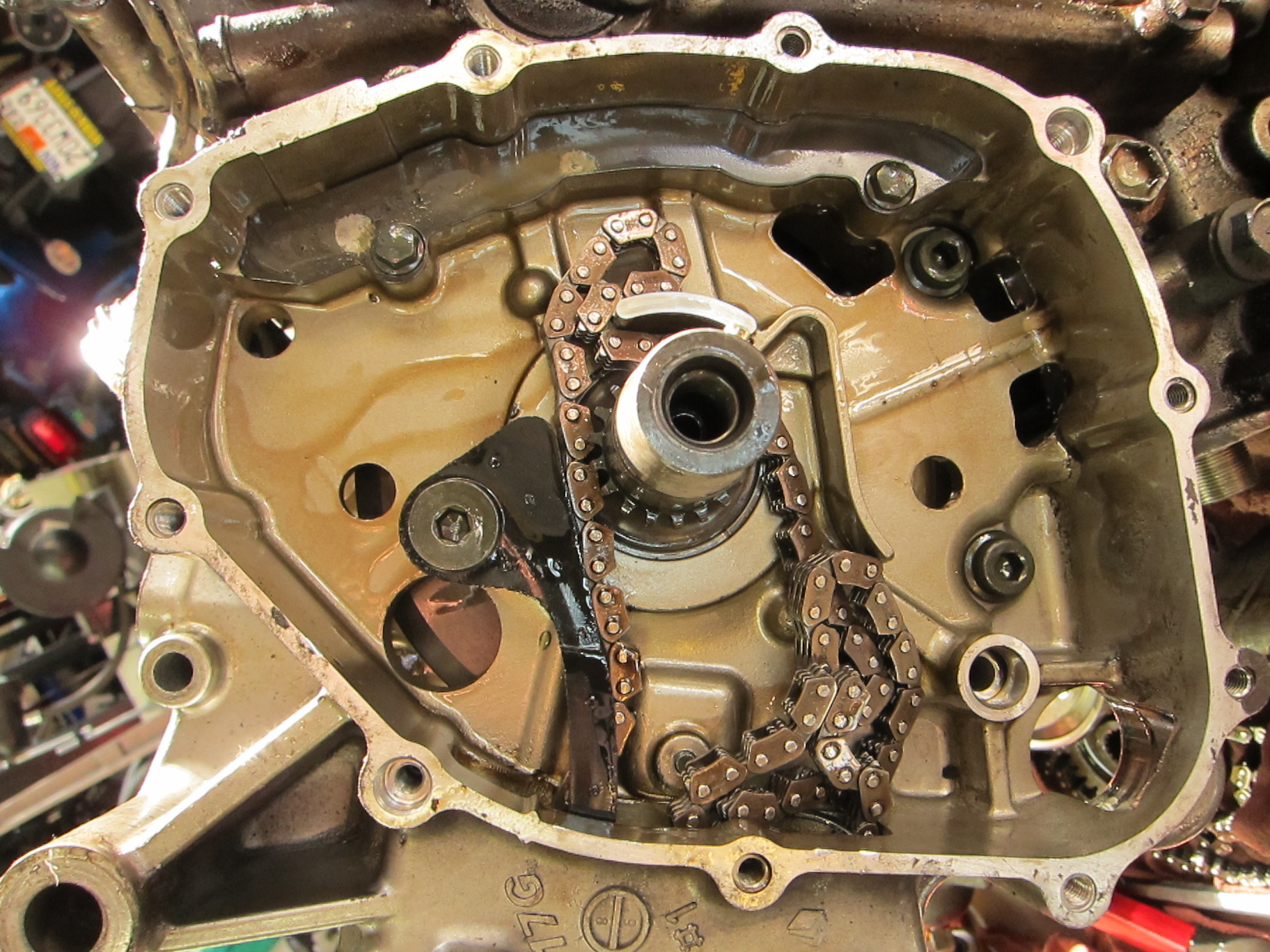
Crankshaft exposed--note loose cam chain
Then there were a few loose ends to clean up before splitting the cases; I pulled the oil pipe and the star gear from the transmission.
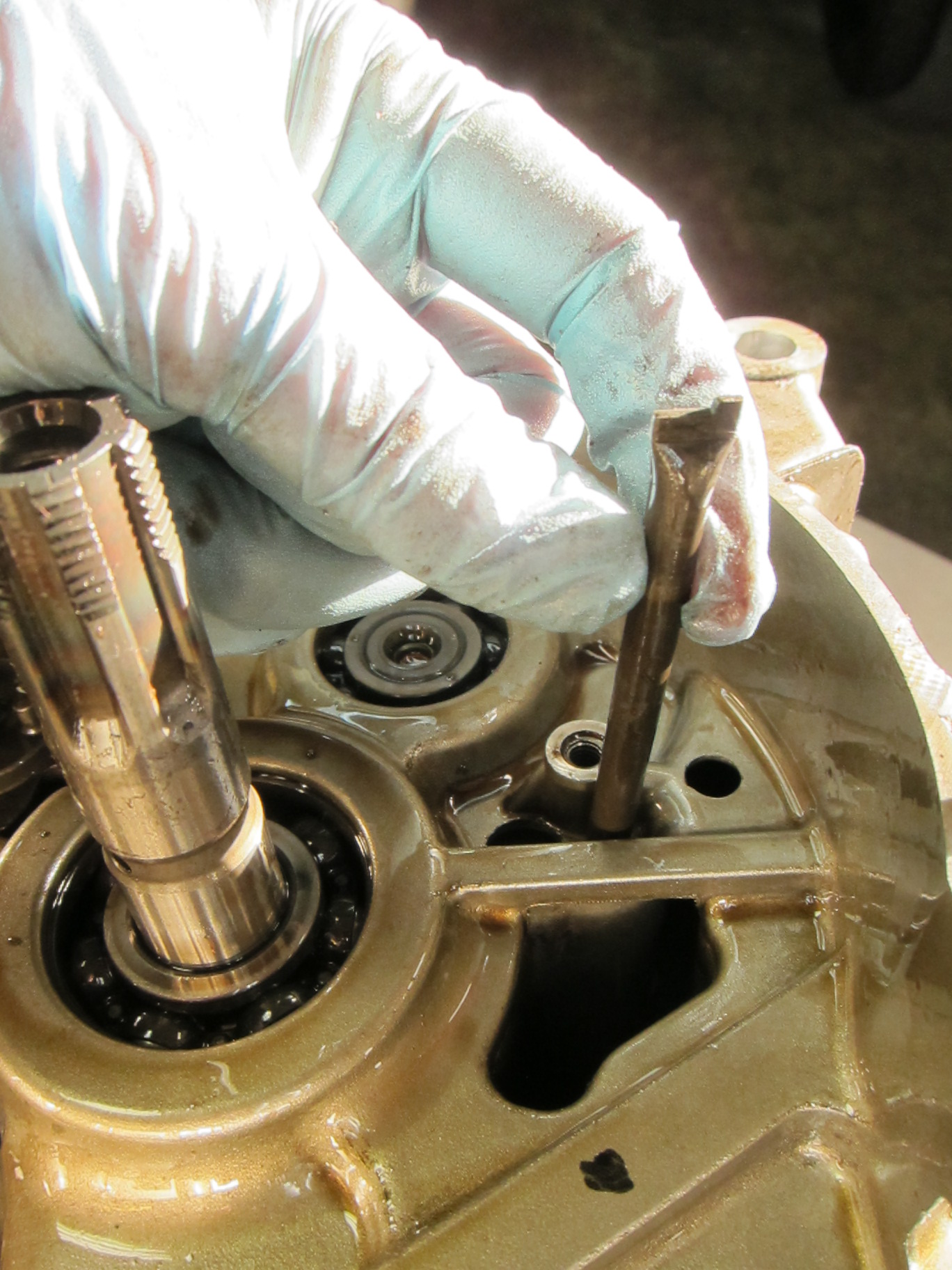
Removing an oil line rod to prep for splitting cases
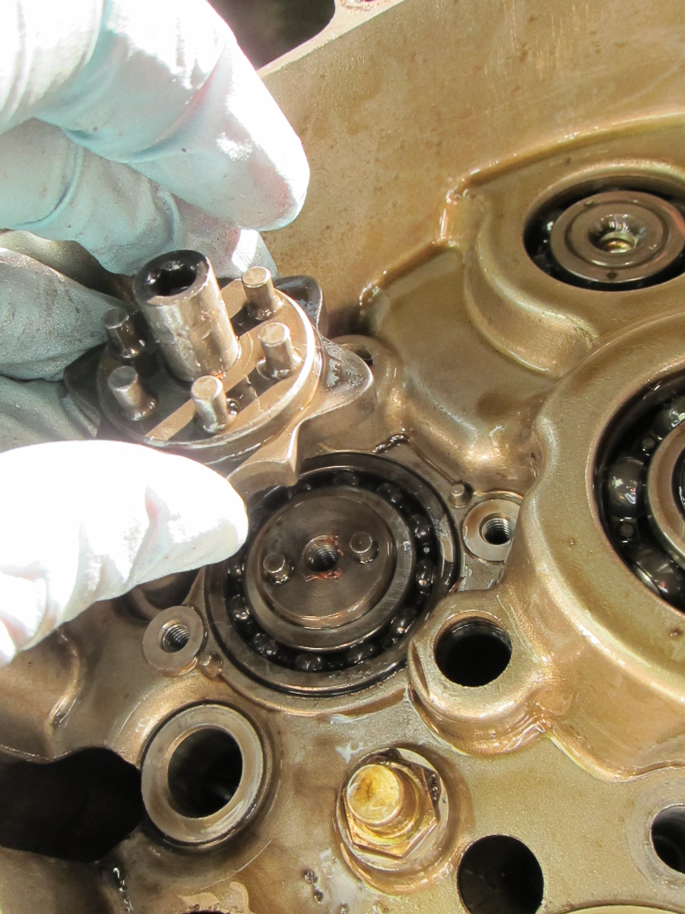
Removing the transmission star gear
And now, the moment I’d been waiting for–it was time to split the cases. It was my first time, prying apart the halves of the engine to get into the bottom end, to penetrate the secrets of its demise; and it felt like a rite of passage into the realm of internal combustion. I gently worked in my miniature pry bar and began to tap the cases apart with the soft-faced mallet.
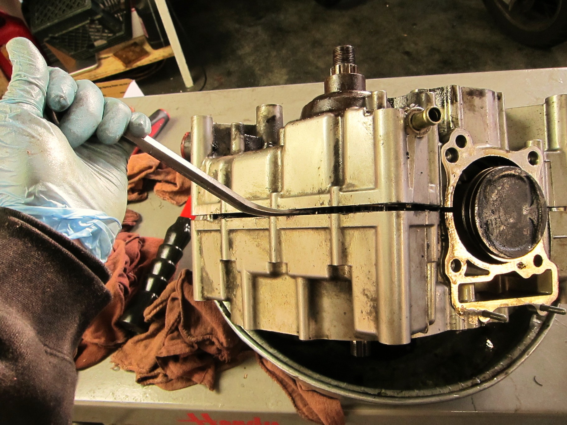
The moment of truth--splitting the cases
With a great deal of tapping and gentle prying, the halves began to pull apart.
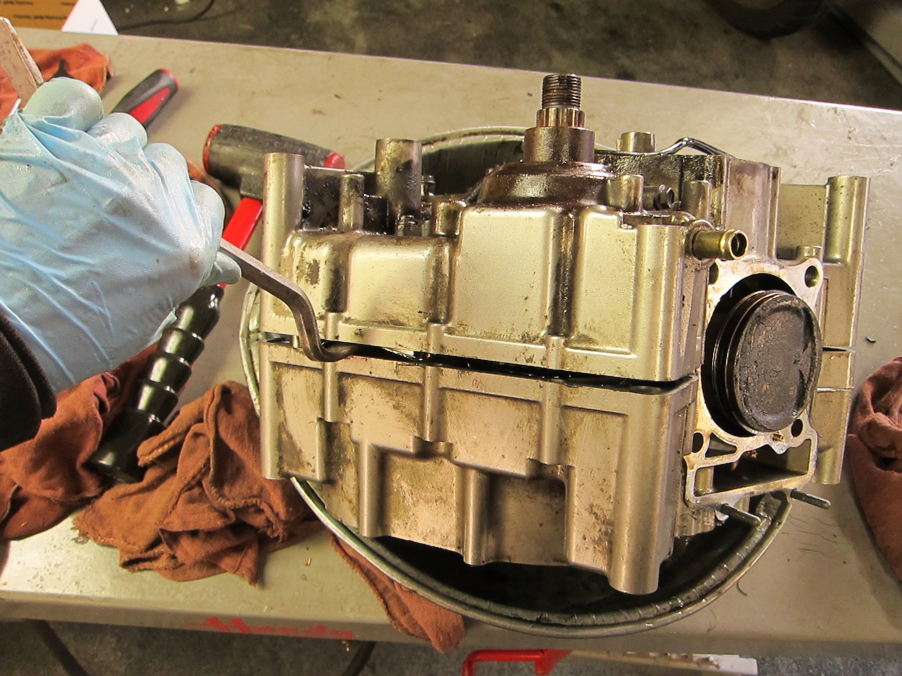
The case halves, coming apart
And at last, the halves of the crankcase fell apart, revealing all that lay within.
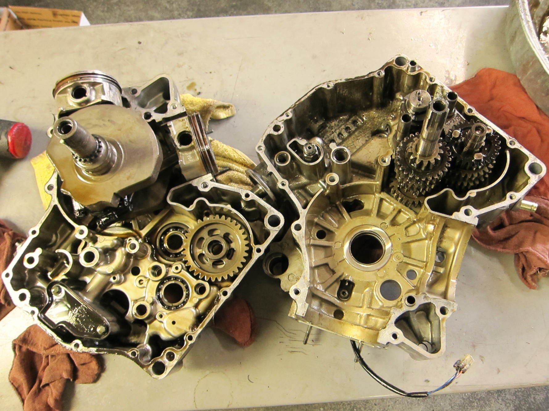
Halves of the crankcase, apart. Note exposed crankshaft on the left.
I lifted out the crankshaft and the pistons.
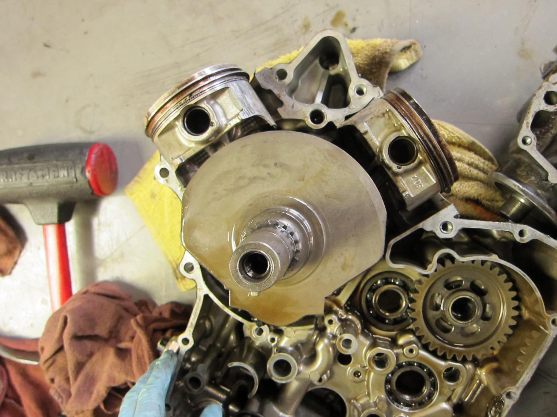
The crankshaft, with pistons attached
In the other half of the crankcase, the transmission gears and dogs were now visible.

Transmission gears
At this point, I began to see sparkly bits of metal deposited on the lower surfaces of the engine–a sure sign of severe lower-end engine damage. Those sparkly bits of metal were torn and sheared off something important…
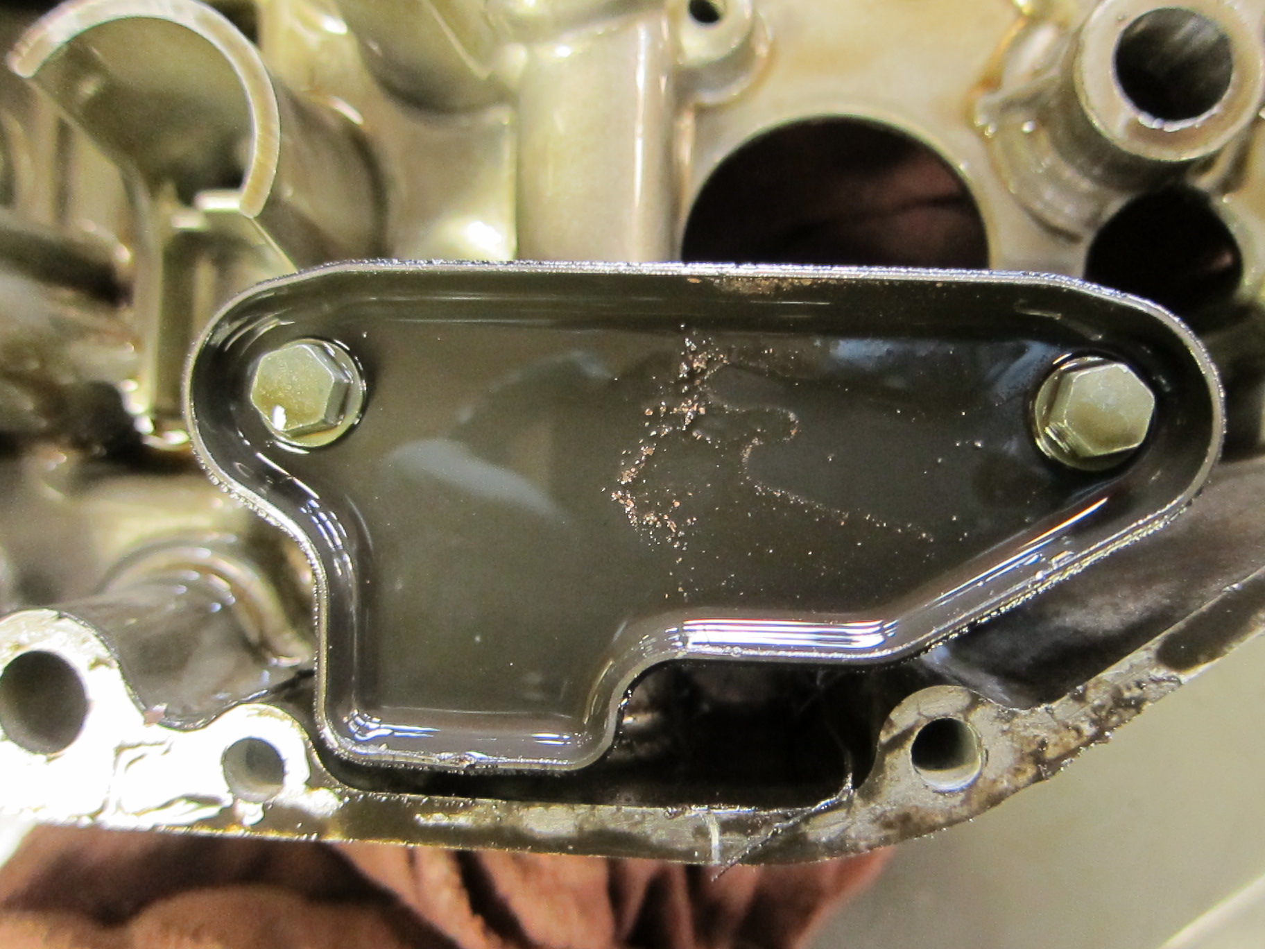
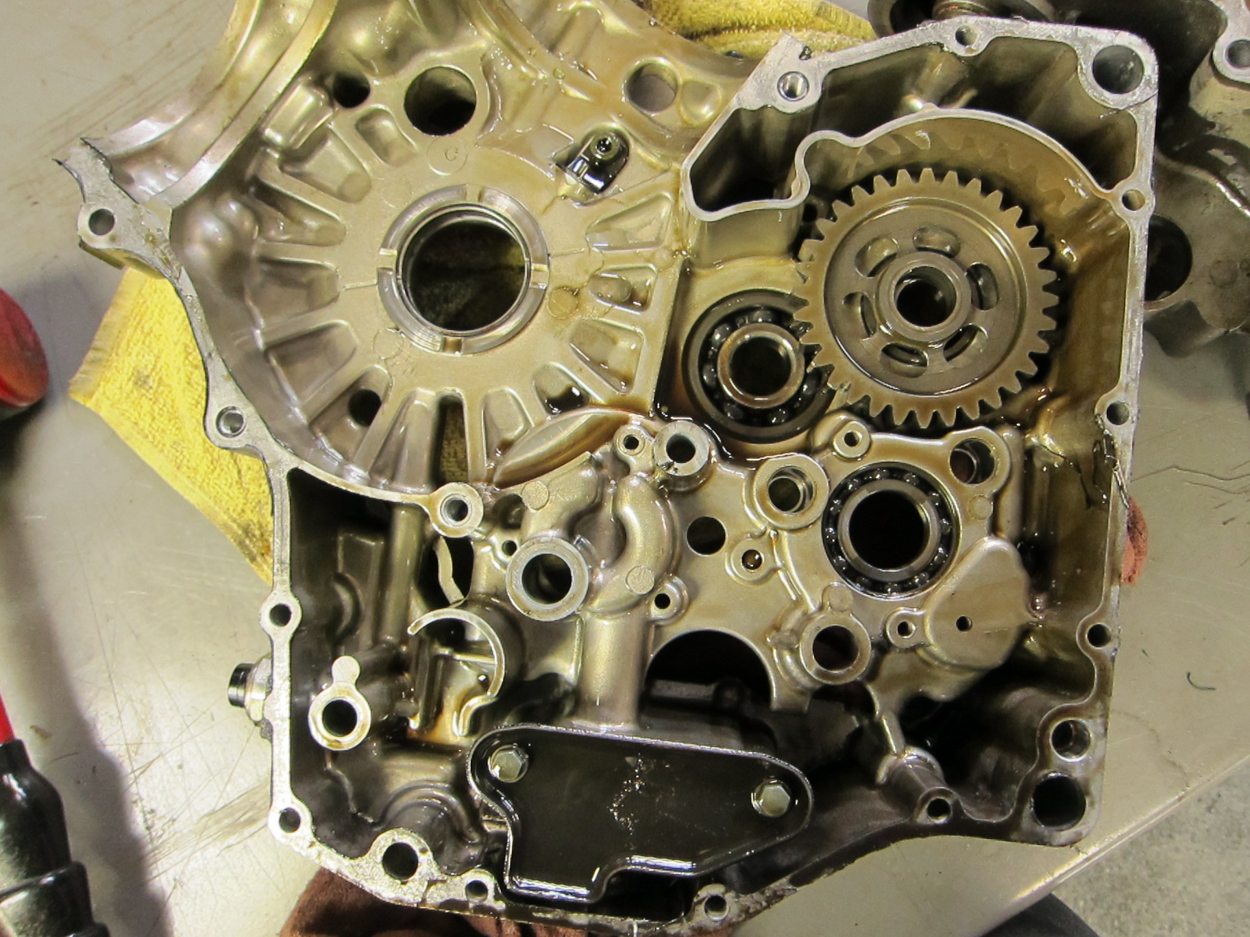
Something exploded into glittery fragments, leaving the residue here.
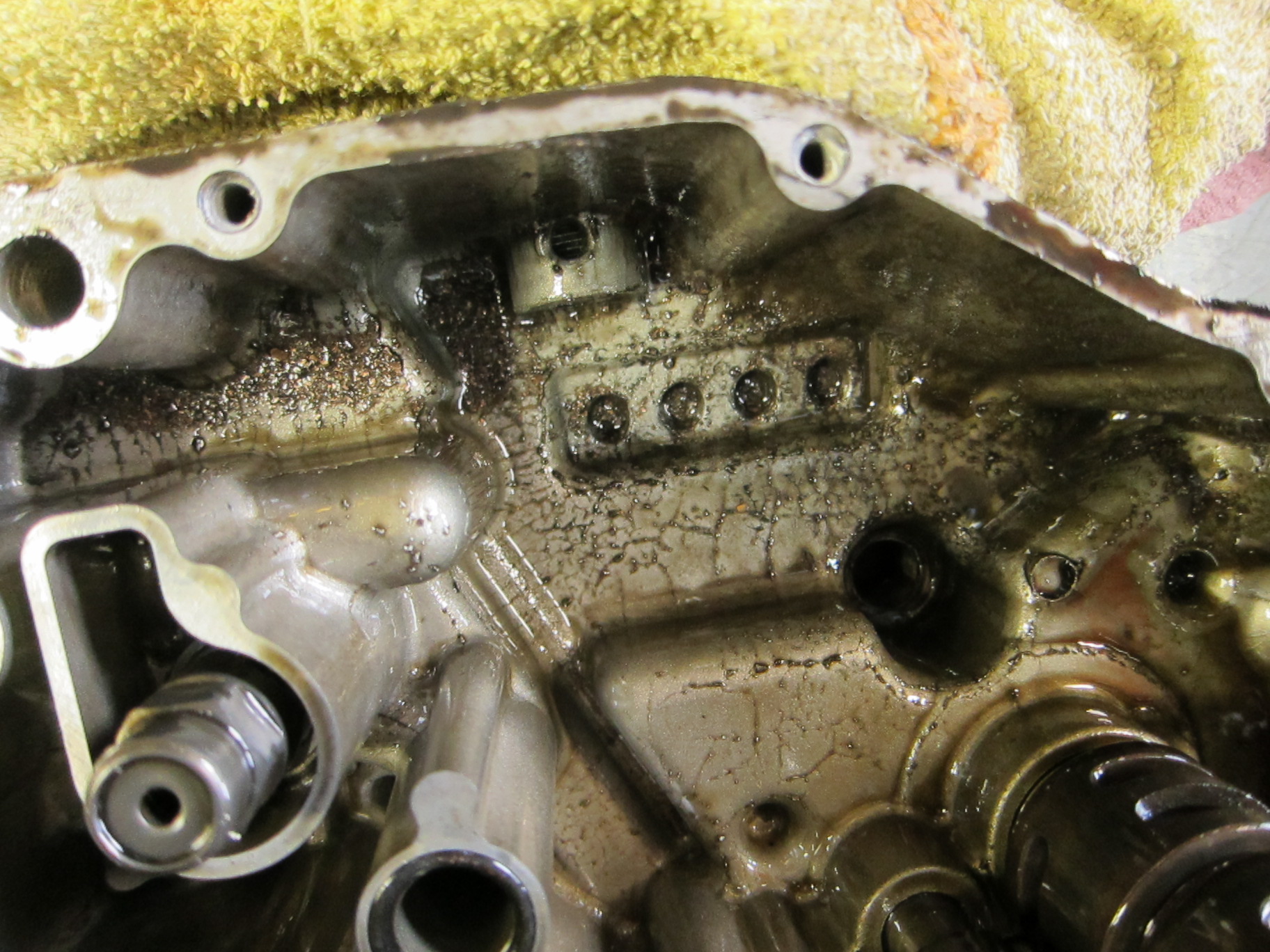
More "sparklies," metal shavings adhering to the bottom end of the engine. They're the result of destruction somewhere in the engine, and the scoring I found earlier was not enough to make this mess.
When the crankshaft came free, the connecting rods (which connect the pistons to the crankshaft) were heat-blackened, showing that they had endured tremendous overheating and abuse.
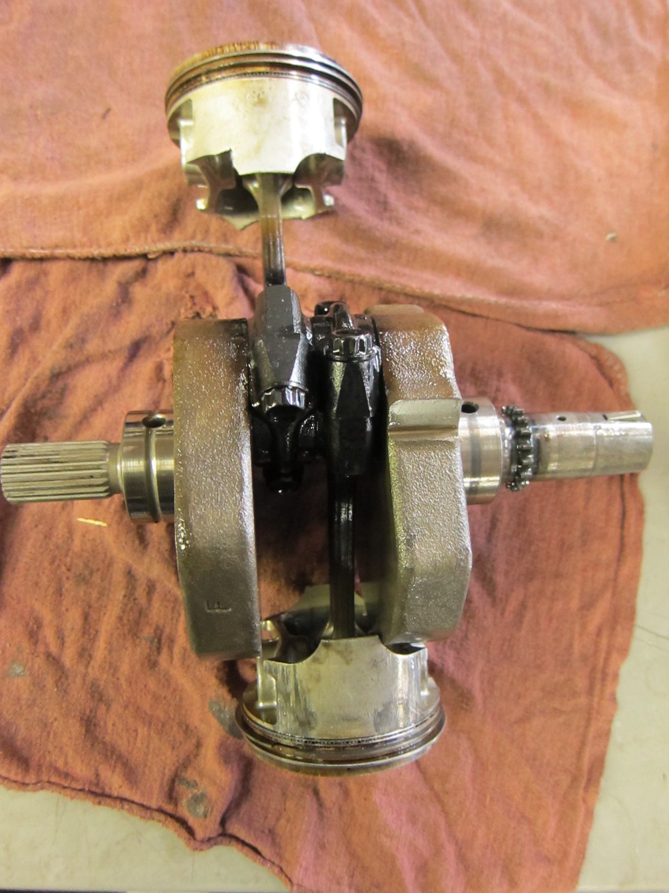
Crankshaft and pistons--note heat blackening on the lower sections of the connecting rods, where they bolt onto the crankshaft
I turned over the crankshaft and unbolted the connecting rods.

End of the connecting rod, with bolts removed
One of the con rods was just beginning to melt together (and the the crankshaft), and had to be pried apart with considerable force. It was another clue to the nature of the problem.
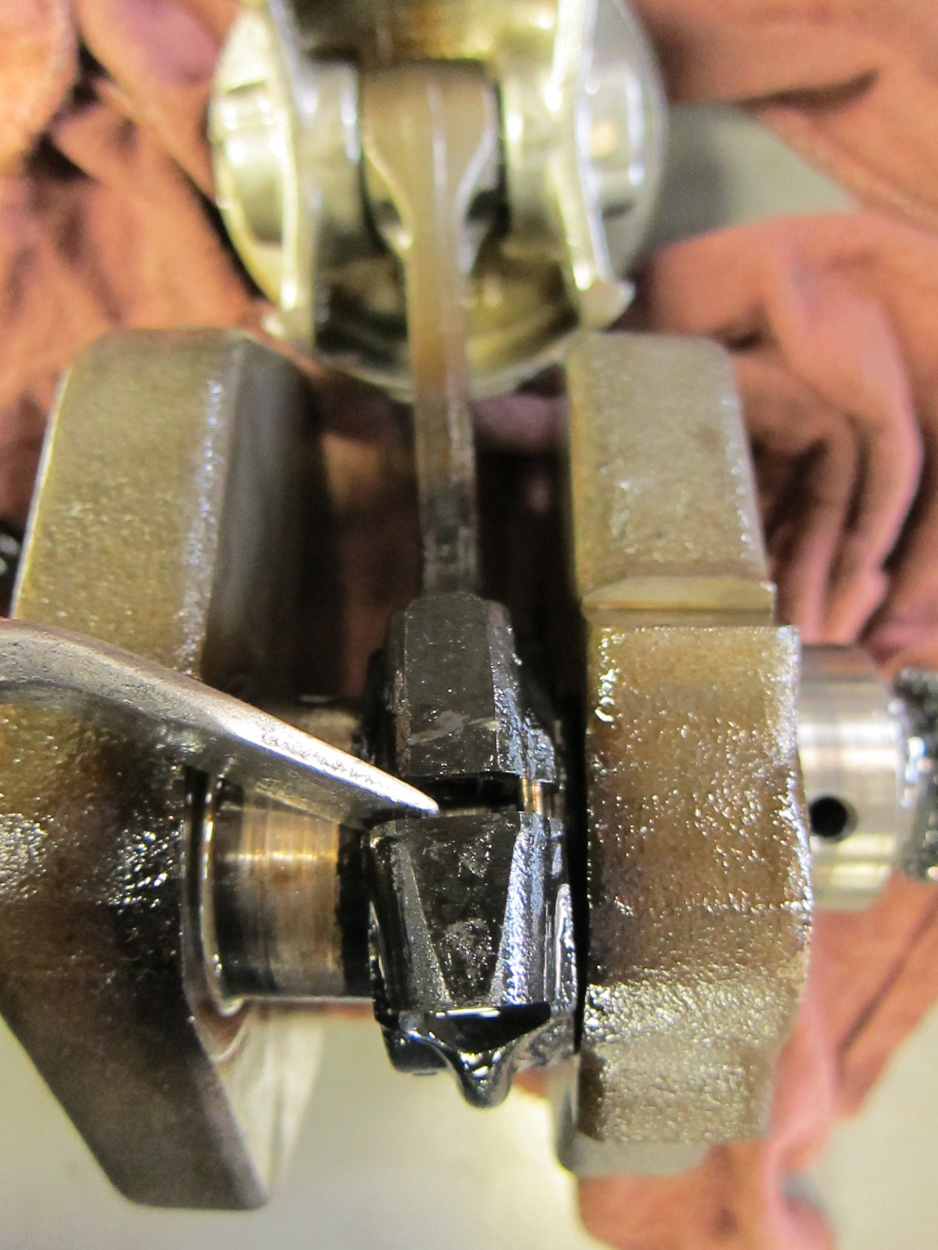
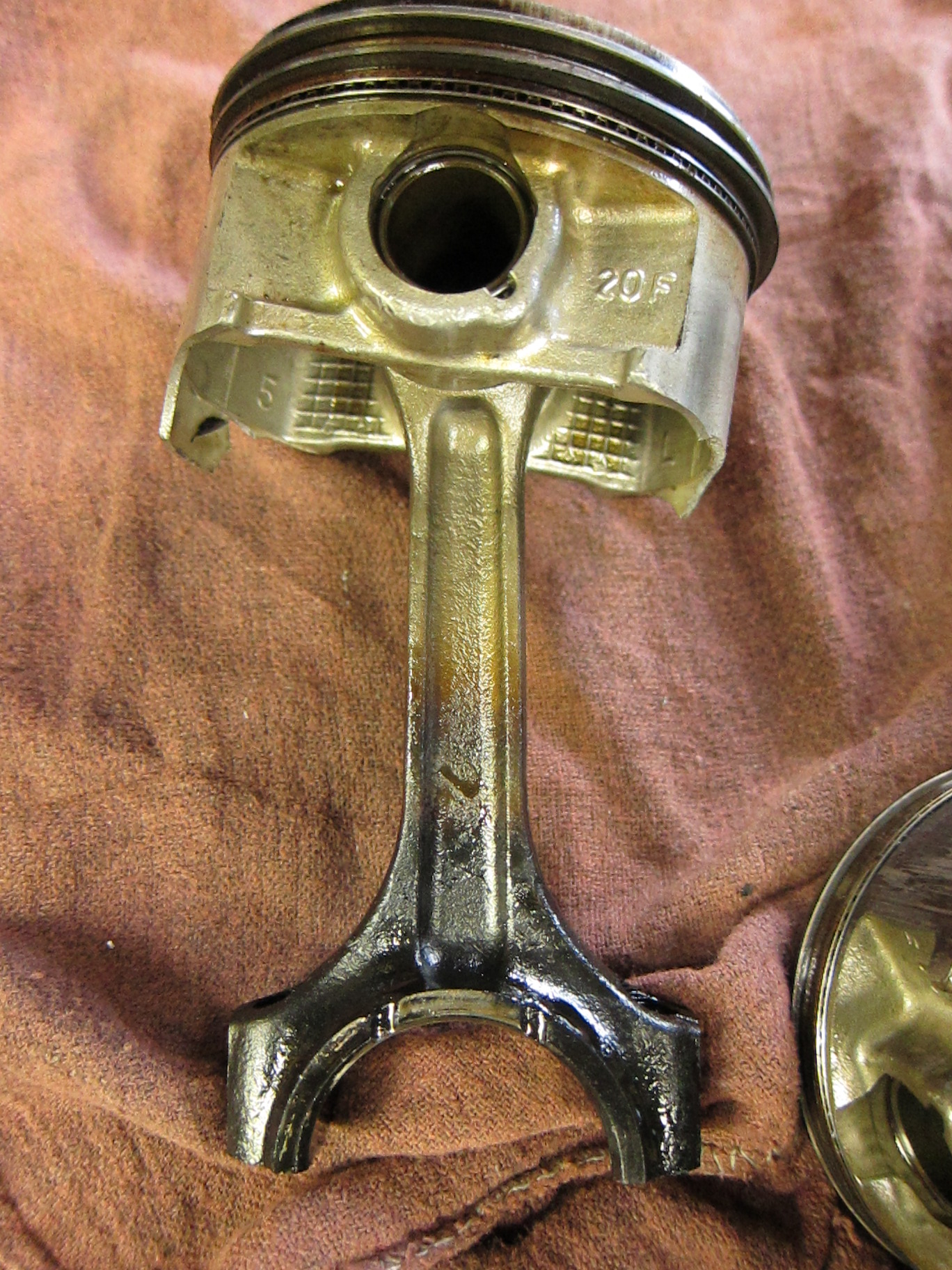
Connecting rod and piston
And when I finally pried off and set aside the pistons and connecting rods, down in the very belly of the beast, the oil-starvation problem suddenly revealed itself. The connecting rod bearings, which glide between the inner surface of each connecting rod and the outer surface of the crankshaft as it spins, had finally lost its protective coating of oil, and began to spin and melt and disintegrate. The scoring can be clearly seen.
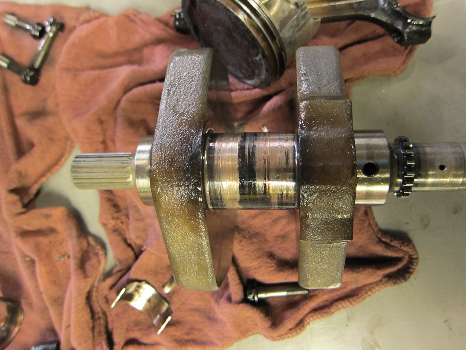
Connecting rod bearings--scored and melted and damaged.
This was the source of all those metal flakes in the lower portions of the engine–the con-rod bearings shredding themselves into oblivion. I pried off the remains of the damaged bearings and took a closer look.
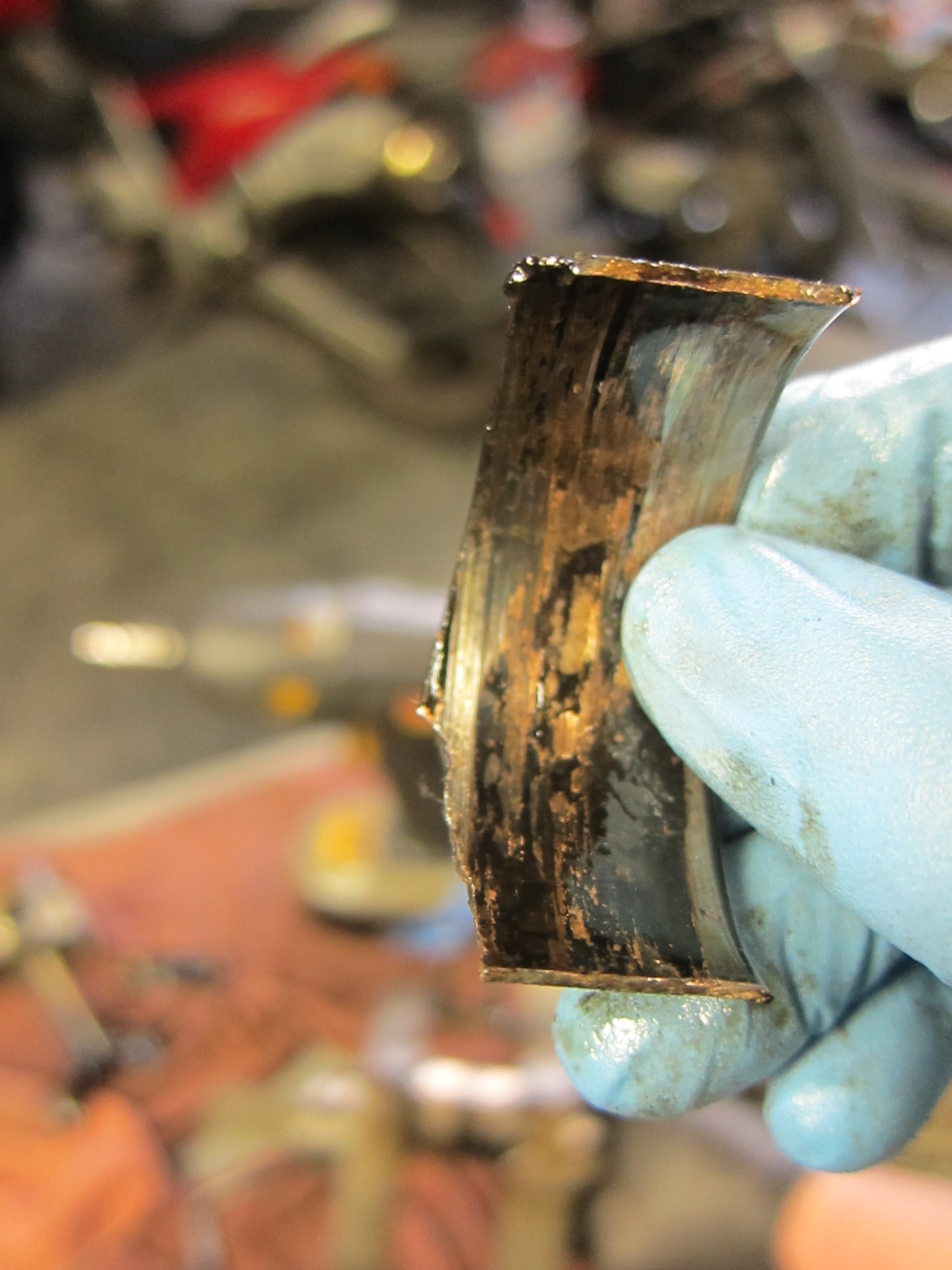
Inner surface of a heavily damaged connecting rod bearing--a classic example of a "spun bearing"
The truth was in there, and it was ugly.
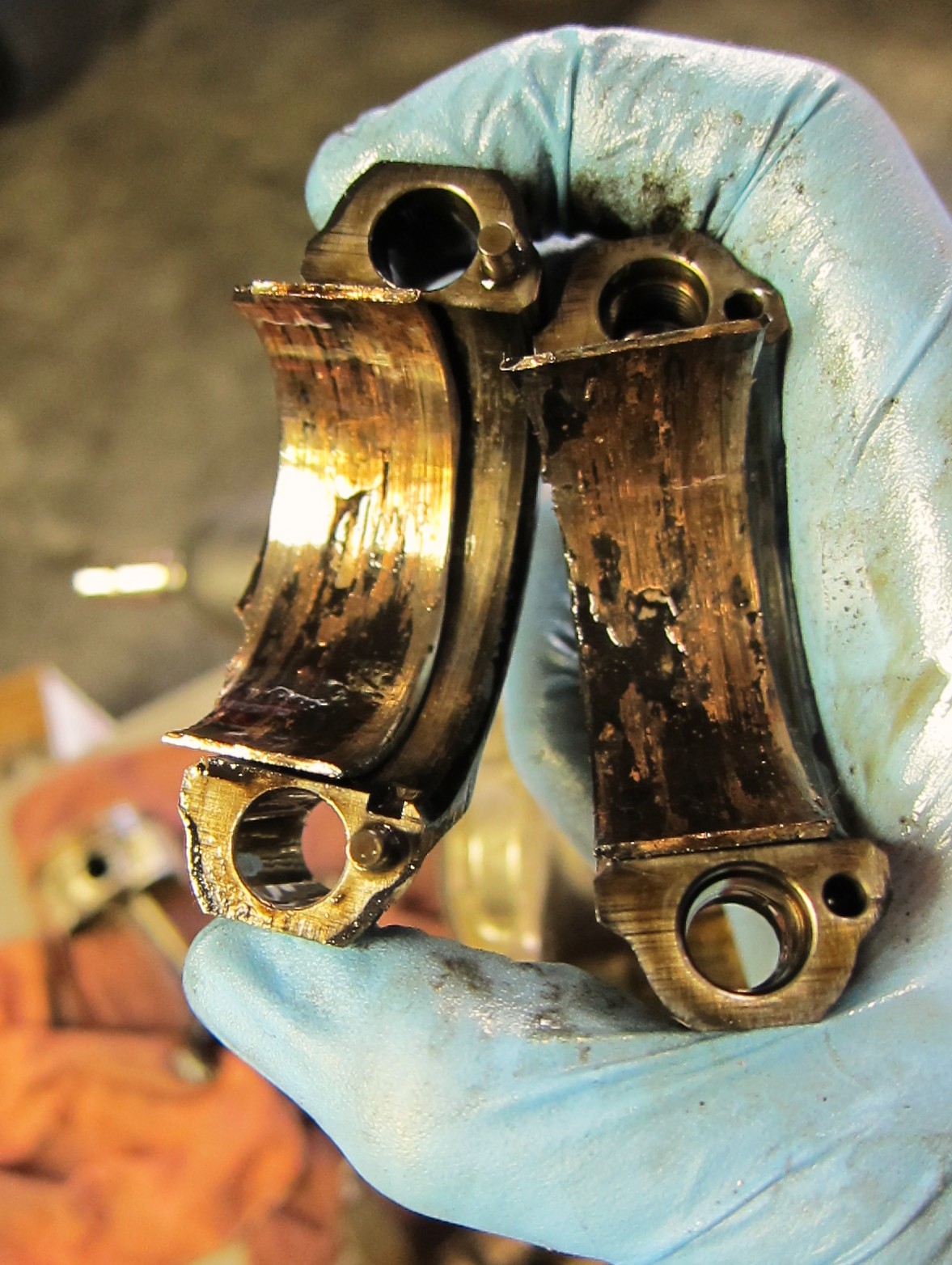
Connecting rods with damaged bearings inside
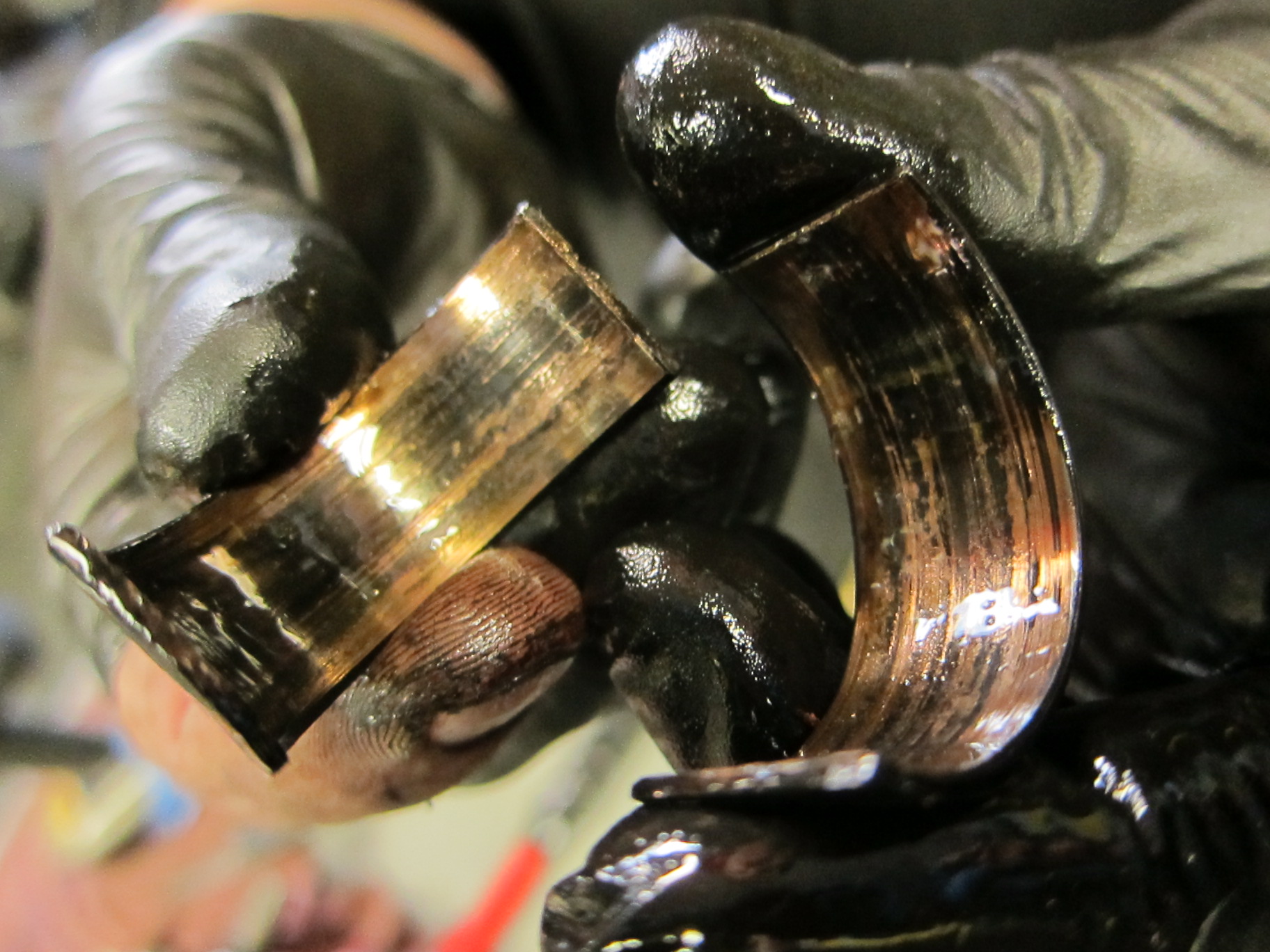
Cause of death: spun bearings
So here before us was the verdict: in addition to the scored piston and cylinder, the doomed V-Strom engine died from a textbook case of spun con-rod bearings. It was a sad death, and a preventable one, but it was a fascinating learning process to deconstruct and diagnose the cause of the engine’s demise.
Remember, oil is the lifeblood of your bike’s engine!
